 |
|||
|
|
|||
|
Page Title:
Table 2-8.4. Speedometer Dip Switch Settings |
|
||
| ||||||||||
|
|
 TM 9-2320-366-20-1
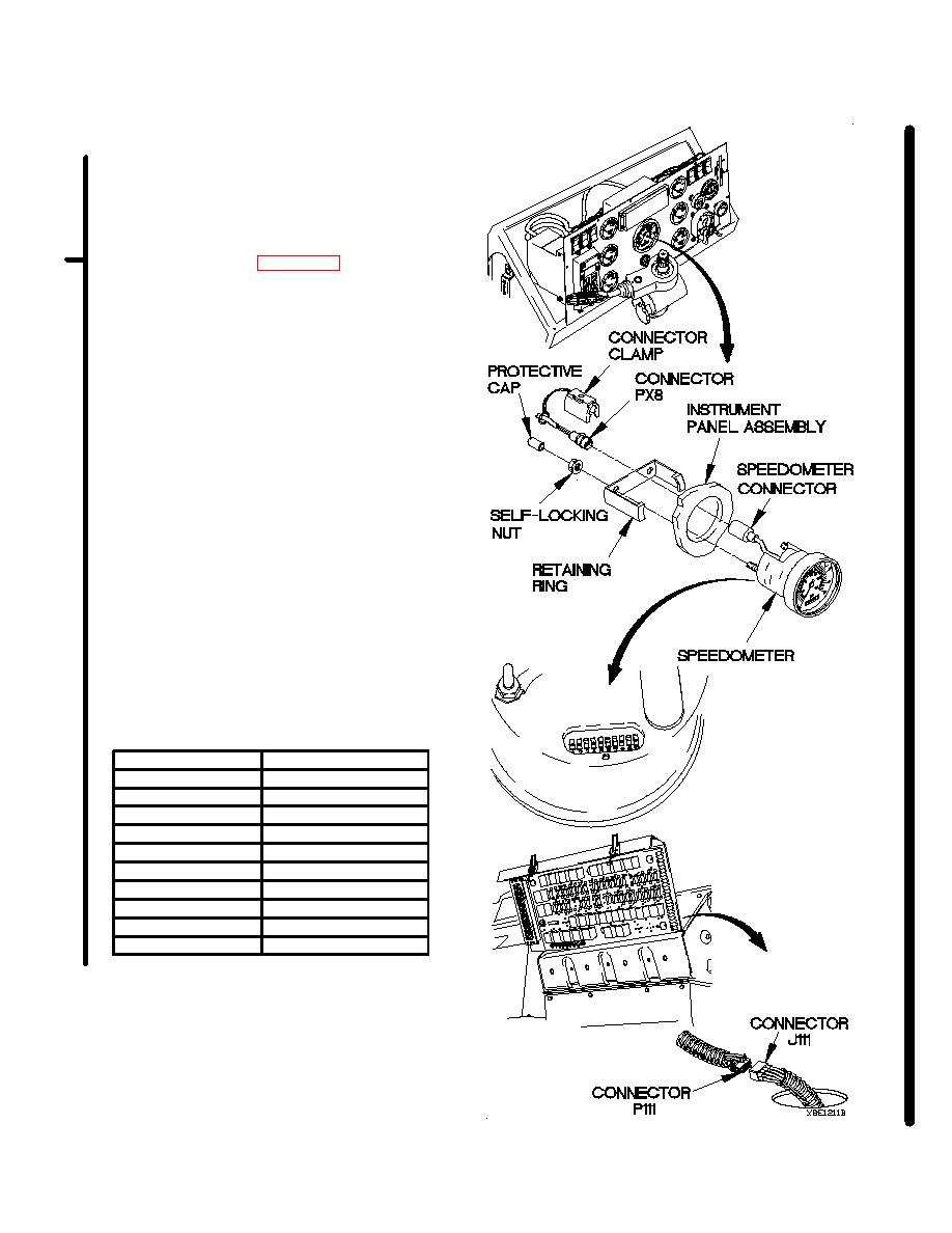
(1) Remove two protective caps, self-locking
nuts, retaining ring, and speedometer from
instrument panel assembly. Discard self-
locking nuts.
(2) Note position of speedometer dip
switches. Refer to Table 2-8.4.
Speedometer Dip Switch Settings.
(3) If speedometer dip switch setting(s) are
incorrect, correct speedometer dip switch
setting(s) (para 7-14).
(4) If speedometer dip switch settings are
correct, replace speedometer (para 7-14).
(5) Position speedometer in instrument panel
assembly with retaining ring and two self-
locking nuts.
(6) Tighten two self-locking nuts to 9 lb-in.
(1 Nm).
(7) Install two protective caps on
speedometer.
(8) Connect connector PX8 to speedometer
connector.
(9) Connect connector clamp on speedometer
connector.
(10) Install instrument panel assembly (para
7-10).
(11) Connect connector P111 to connector
J111.
(12) Install PDP on dashboard with three
washers and screws.
(13) Install three screws in PDP.
(14) Install PDP cover (TM 9-2320-366-10-2).
Switch Number
Switch Setting
1
Up
2
Up
3
Down
4
Up
5
Up
6
Down
7
Down
8
Up
9
Down
10
Up
Change 1
|
|
Privacy Statement - Press Release - Copyright Information. - Contact Us |
