 |
|||
|
|
|||
|
|
|||
| ||||||||||
|
|
 TM 9-2320-279-20-1
Electrical System Maintenance Instructions (Cont)
d.
Installation.
NOTE
Support battery box while doing
steps (1), (2), and (2.1).
Bracket spacers on frame are only
used on M984, M1120-LHS and
M1977-CBT. All other models use
flat spacers. On M983 there are six
spacers used.
Do step (2.1) for M1120-LHS only.
Do step (2.2) for M1977-CBT only.
Do step (2.3) for M1120-LHS and
M1977-CBT only.
M1977-CBT has eight holes on back
wall of battery box. Only four holes
will be used for mounting. All other
models use six screws.
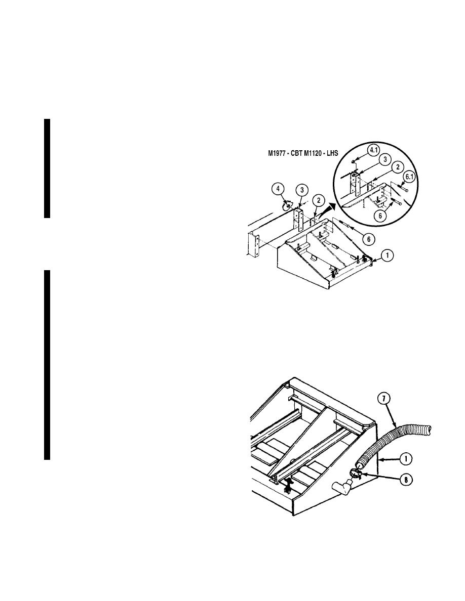
(1)
Soldier A and Soldier B position battery
box (1) and flat spacers (2) or two
bracket spacers (3) against frame.
(2)
Soldier A installs six nuts (4) while
Soldier B installs six screws (6) in back
of battery box (1) through flat spacers
(2) or bracket spacers (3).
(2.1) Soldier A installs five nuts (4) while
Soldier B installs five screws (6) in back
of battery box (1) through bracket
spacers (3).
(2.2) Soldier A installs four nuts (4) while
Soldier B installs four screws (6) in
upper back of battery box through flat
spacers (2).
(2.3) Soldier A installs one nut (4.1) while
Soldier B installs screw (6.1) in back of
battery box (1) through bracket spacer
(3).
NOTE
Do step (3) for arctic kit battery box only.
(3)
Install exhaust pipe (7) on battery
box (1) with hose clamp (8).
Change 7
|
|
Privacy Statement - Press Release - Copyright Information. - Contact Us |
