 |
|||
|
|
|||
|
Page Title:
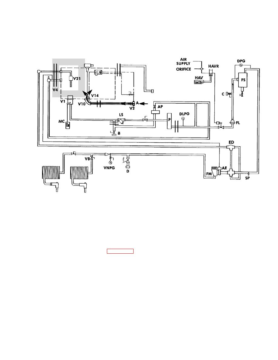
Figure 2-13. Tanker Operation Functional Diagram (Sheet 12 of 12). |
|
||
| ||||||||||
|
|
 TM 9-2320-279-20-1
Troubleshooting Malfunctions (Cont)
Table 2-9. Troubleshooting (Cont)
BOTTOM LOAD (EXTERIOR PUMP - 600 GPM)
In the operation above, the tanker is filled from a reservoir which has its own pump able to transfer fuel at
rates up to 600 GPM. Receptacle A feeds directly into the tanker. The fuel can only flow through recep-
tacle A when valve V10 is open. Valve V10 opens as soon as the fuel pressure is available at receptacle A
unless the level of the fuel in the tank is at its maximum level. This serves as an automatic shut-off so that
when the fuel level rises to the full level valve V10 closes preventing the tank from being over-filled.
NOTE
Refer to Figure 2-11 for tanker component identification.
Figure 2-13. Tanker Operation Functional Diagram (Sheet 12 of 12).
Change 4
|
|
Privacy Statement - Press Release - Copyright Information. - Contact Us |
