 |
|||
|
|
|||
|
Page Title:
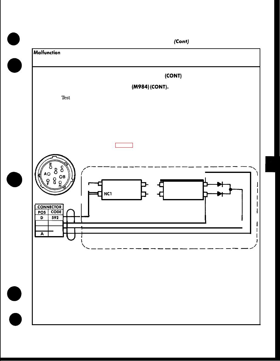
Figure 2-8. Winch Controller Wiring Diagram. |
|
||
| ||||||||||
|
|
 TM 9-2320-279 -20-1
Troubleshooting Malfunctions (Cent)
Table 2-9. Troubleshooting
Test or Inspection
Corrective Action
HEAVY-DUTY WINCH
1. WINCH CABLE WILL NOT PAY OUT
Step 2.
for defective winch controller. Test resistance between cable connector sockets A
and D when pressing OUT switch on controller.
If resistance is zero ohms, go to Step 6.
If resistance is more than zero ohms, go to Step 3.
Step 3. Remove controller cover. Test resistance on wire No. 682 between connector socket A and
IN switch terminal NC1.
If resistance is more than zero ohms on either wire, replace defective wire
(para 17-24 and fig. 2-8).
IN
OUT
I
q
N04
NC1
N03
279
NC2
279
279
NC2
N03
N04
681
B
I
1
I
G
849
682
TA 188038
2-179
|
|
Privacy Statement - Press Release - Copyright Information. - Contact Us |
