 |
|||
|
|
|||
|
|
|||
| ||||||||||
|
|
 TM 5-5420-279-23
a.
Remove
(1)
De-pressurize the hydraulic system. Refer to unit maintenance procedure 5-118.
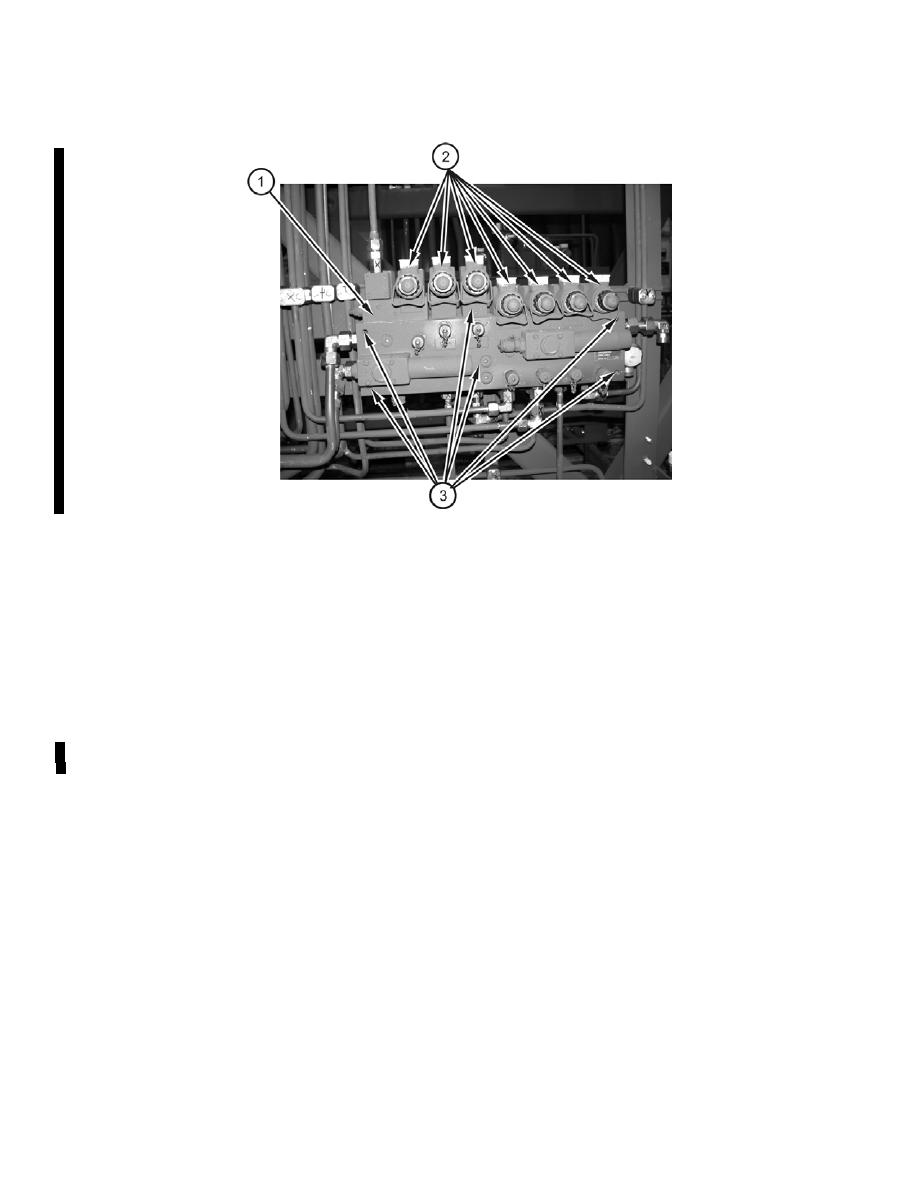
(2)
Remove the right hand launch frame guard to gain access to the pilot manifold assembly
(1). See operator's maintenance TM 5-5420-279-10 chapter 10.
(3)
Note the position of and disconnect the hydraulic pipe work connected to the pilot manifold
assembly.
(4)
Note the position of and remove the electrical connections (2) on the pilot manifold
solenoid valves.
(5)
Support the weight of the pilot manifold assembly (1).
(6)
Remove the six mounting bolts, nuts and washers (3) securing the pilot manifold assembly
(1) from the back side to the launch frame.
(7)
Remove the pilot manifold assembly (1).
(8)
Note the position of and remove all hydraulic valves, valve blocks, test points, blanking
plugs and blanking flanges.
(9)
Fit the hydraulic valves, valve blocks, test points, blanking plugs and blanking flanges to
the new manifold assembly using new gaskets and O-rings where applicable.
b.
Install
(1)
Fit the Pilot Manifold Assembly (1) to the Launch Frame.
(2)
Secure the Pilot Manifold Assembly using the six bolts, nuts and washers (3).
(3)
Fit the electrical connections (2) in the positions noted during removal.
(4)
Fit the hydraulic connections to the positions noted during removal.
(5)
Check and top up, if necessary, the hydraulic oil level at the hydraulic reservoir.
|
|
Privacy Statement - Press Release - Copyright Information. - Contact Us |
