 |
|||
|
|
|||
|
|
|||
| ||||||||||
|
|
 TM 11-6625-564-45
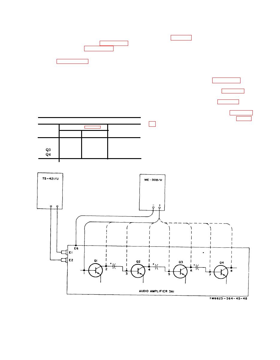
c. Stage Gain Measurements. Use the pro-
(2) If the gains of the stages are abnor-
mally low, use isolating techniques
cedures given below when audio amplifier
3A1 is believed to be defective. Stage gain
tive part within the stage.
test points are indicated in figure 2-30. Parts
location are given in figures 2-26 and 2-27.
2-9. lsolating Troubles
(1) Connect. the equipment as shown in
When trouble has been localized to audio
amplifier 3A1, use the techniques listed below
and measure between the test points,
to isolate the defective part:
listed in the chart below, and chassis
a. Take voltage measurements at the termi-
ground. Adjust the audio oscillator
nals of 3A1 as indicated in figure 2-29.
for 0.1-volt ac output at. 3 kc. Com-
b. If the voltage indications are normal,
pute the gain for each stage by divid-
take resistance measurements (fig. 2-29) to
ing the measured Output voltage by
isolate open or short circuits. Refer to the re-
the measured Input voltage. The
sistance and continuity chart (para 2-7c) and
gain should be as listed in the chart
to the dc resistance of transformers d below.
below.
c. Use the schematic diagrams (fig. 4-10
and 4-11) and the wiring diagrams (fig. 2-
Audio amplifier 3A1
ther isolate the faulty part.
stage
Stage gain
Input
Output
Caution:
Take resistance readings only
with Multimeter ME-26B/U. The de source
Q1
1
2
2.5
in some multimeters can destroy the transis-
Q2
3
4
2.8
tors by causing excessive current through
5
6
1.3
7
8
5.3
them.
Figure 2-30. Test unit audio amplifier 3A1, stage gain test setup diagram.
55
|
|
Privacy Statement - Press Release - Copyright Information. - Contact Us |
