 |
|||
|
|
|||
|
|
|||
| ||||||||||
|
|
 TM 11-6625-2609-34
(8) One length of cable.
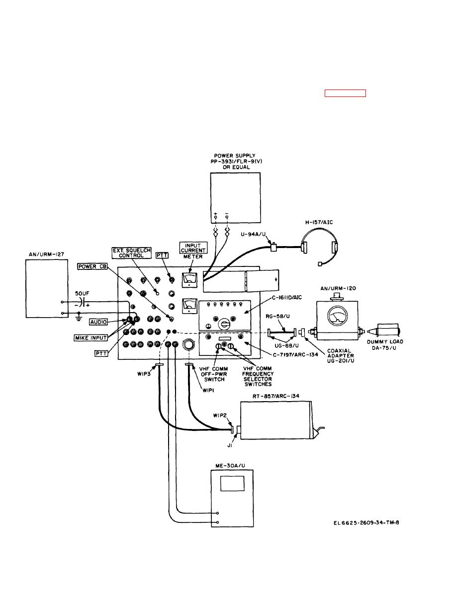
3-16. Detector Circuit Check
a. Test Equipment and Material.
(9) Capacitor, 50 uf, 25 vdc.
(1) Radio Set AN/ARC-134.
(.l o ) Dummy Load, Electrical DA-75/U.
,
(2) Power supply.
b. Test Connections and Conditions. C o n n e c t
the equipment as shown in figure 3-7. Place the
120.
C-1611D/AIC transmit-interphone selector switch
(4)
Generator, Signal AN/URM-127.
in position 3, the RECEIVERS 3 switch ON, all
Voltmeter, Electronic ME-30A/U.
(6)
other RECEIVERS switches off. and position the
(6)
Adapter.
VOL control as required. These settings must be
(7)
Two coaxial connectors.
maintained during the test.
Figure 3-7. Detector circuit, test setup.
3-18
|
|
Privacy Statement - Press Release - Copyright Information. - Contact Us |
