 |
|||
|
|
|||
|
Page Title:
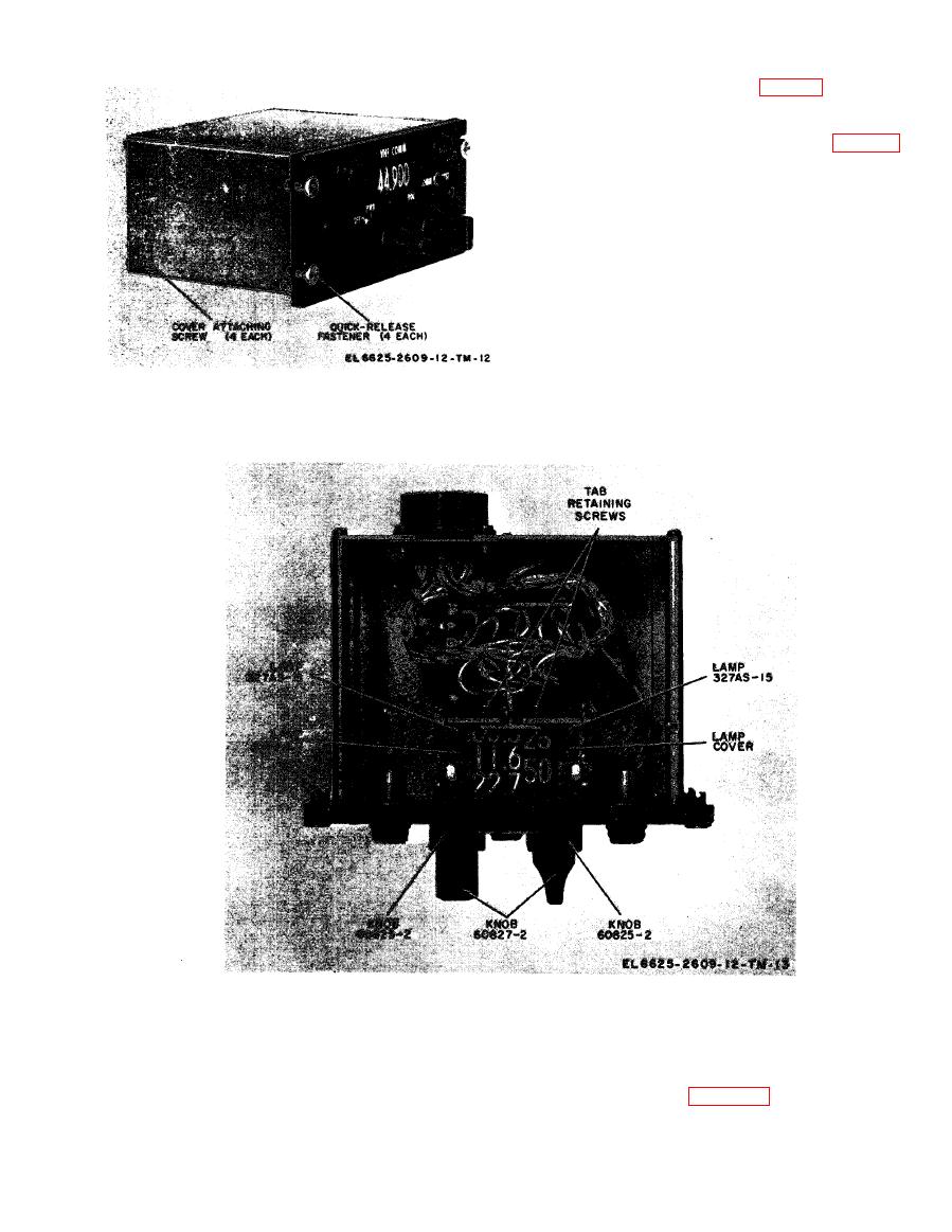
Figure 3-2. Radio control disasembly. |
|
||
| ||||||||||
|
|
 TM 11-6625-2609-12
d. Remove the lamp cover (fig. 3-3) from the
dial indicator lamp.
e. Loosen the tab retaining screw (fig. 3-3)
near the lamp base.
f. Turn the retaining tab away from the lamp
base.
g. Push the lamp backward through the hole
in the gear plate and remove the lamp.
h. Insert a new lamp in the gear plate.
i. Position the retaining tab over the base of
the lamp and tighten the retaining screw.
j. Replace the lamp cover over the lamp.
Section VI. TESTING
checks and services of table 3-2 should be per-
3-9. General
formed to insure that the equipment is function-
After repairs have been made on t h e mainte-
nance kit, the monthly preventive maintenance
ing correctly.
|
|
Privacy Statement - Press Release - Copyright Information. - Contact Us |
