 |
|||
|
|
|||
|
Page Title:
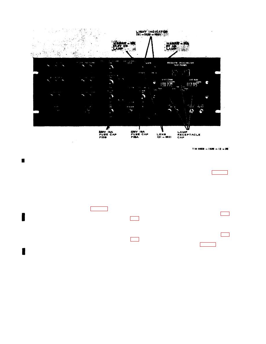
Figure 3-1. Test panel, unmodified, indicator lamps and fuse locations. |
|
||
| ||||||||||
|
|
 TM 11-6625-1635-12
C1
Figure 3-1. Test panel, unmodified, indicator lamps and fuse locations.
(1) Rotate lamp receptacle caps (fig. 3-1)
(2) Extract the defective lamp from the
c o u n t e r c l o c k w i s e and remove them from the
lampholder; use a knife blade or small
front panel.
screwdriver as a pry if the bulb is difficult to
(2) Insert a new lamp into the lamp
remove.
receptacle cap and rotate the cap clockwise until
( 3 ) Install a new lamp and rotate the
it is secure.
lampholder clockwise until it is secure.
d. Replacement of Frequency Counter Dial
b. Replacement of Test Panel Fuses.
I n d i c a t o r Lamps.
(1) Rotate the quick-release fasteners (fig.
t e r c l o c k w i s e until it separates from the fuse
holder on the test panel.
(2) Slide the radio control forward and out
(2) Extract the defective fuse from the fuse
of the test panel.
holder.
(3) Remove the cover attaching screws (fig.
(3) Install a new fuse in the fuse holder.
(4) Replace the fuse cap on the fuse holder
(4) Remove the lamp cover (fig. 3-2) from
and rotate the cap clockwise until it is secure.
the dial indicator lamp.
c. Replacement of Radio Control and In-
tercom Control Panel Lamps.
3-6
|
|
Privacy Statement - Press Release - Copyright Information. - Contact Us |
