 |
|||
|
|
|||
|
|
|||
| ||||||||||
|
|
 TM
9-2815-210-34-2-2
FRAME 6
1.
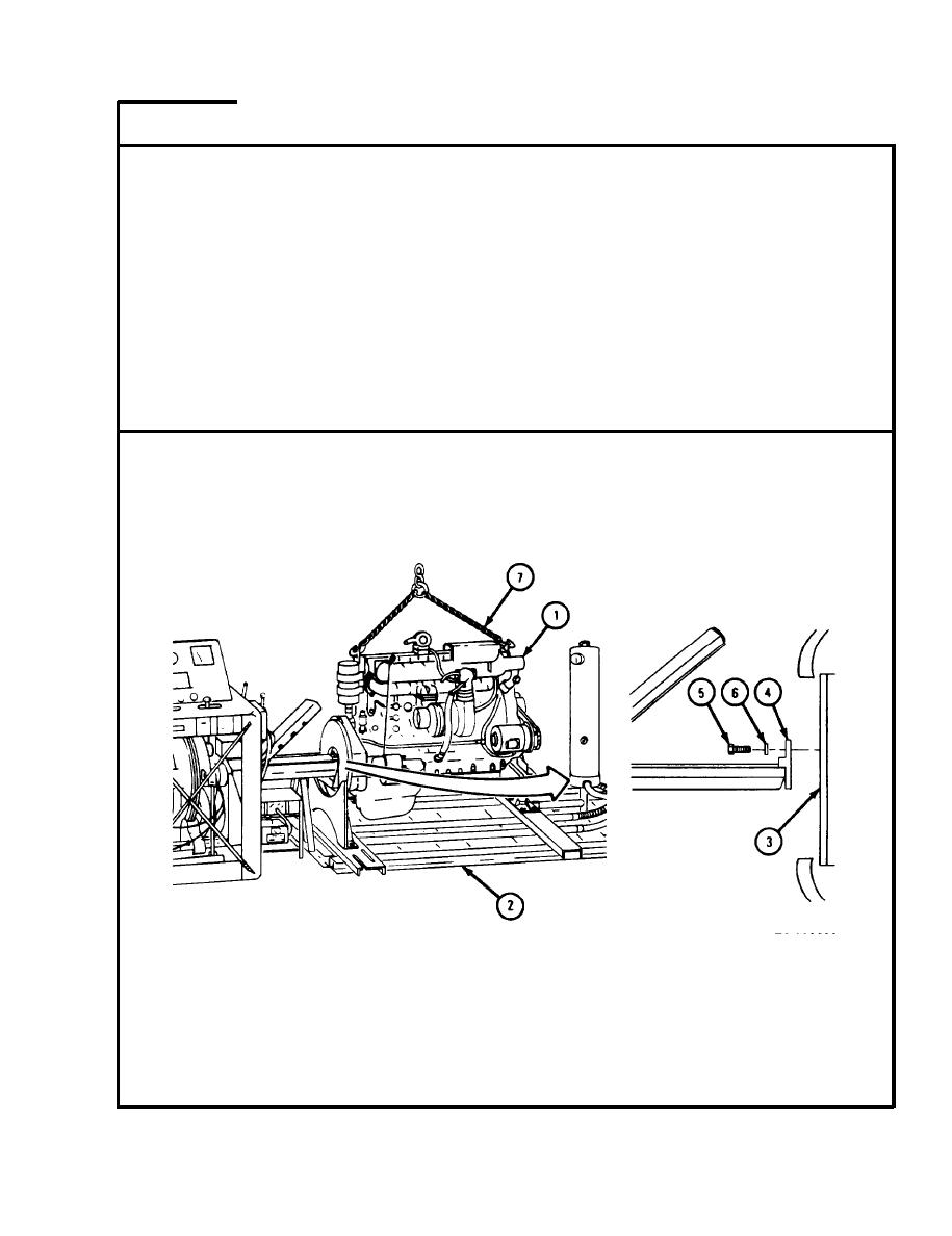
U s i n g hoisting equipment, raise engine assembly (1) just enough
Soldier A
t o take weight off dynamometer test stand (2).
2.
S l i d e engine assembly (1) to the rear until eight screw holes in
Soldiers
A and B
f l y w h e e l adapter (3) are alined with screw holes in drive shaft
(4).
Soldier A
3.
H o l d drive shaft (4) in place so screw holes stay alined.
Soldier B
Put in eight bolts (5) and lockwashers (6). Do not tighten
4.
bolts .
L o w e r engine assembly (1) all the way down and take off chain
Soldier A
5.
sling (7) .
GO TO FRAME 7
TA 118633
6-15
|
|
Privacy Statement - Press Release - Copyright Information. - Contact Us |