 |
|||
|
|
|||
|
|
|||
| ||||||||||
|
|
 TM 9-2815-210-34-2-2
FRAME 2
WARNING
Smoking, sparks or open flames are not allowed within 50
f e e t of work area during this task. Fire or explosion
c o u l d occur, causing injury to personnel and damage to
equipment.
1.
R e f e r to test setup given in paragraph 4-68d frame 1.
2.
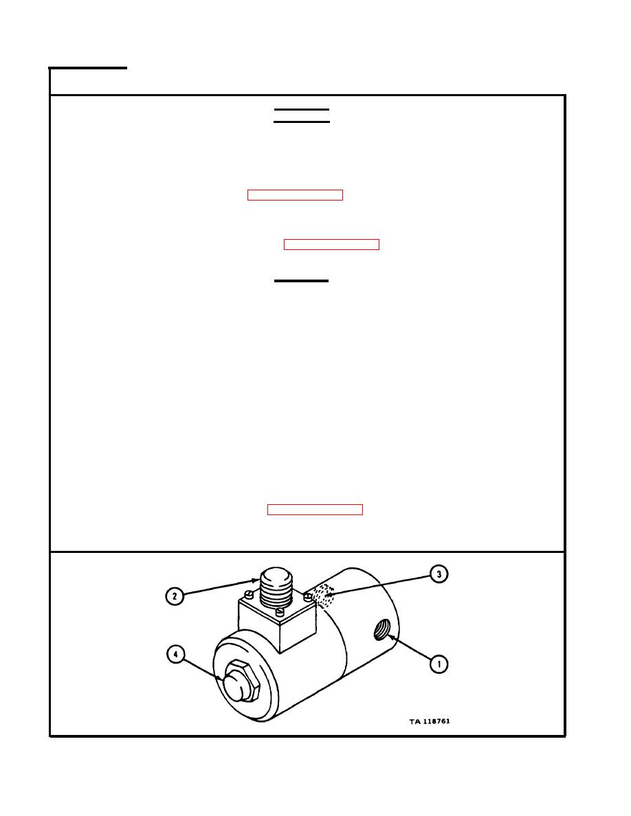
U s i n g suitable fitting, hook up solenoid valve inlet opening (1) in place of
n o z z l e and check valve assembly, shown in test setup.
C o n t i n u e with procedures given in paragraph 4-68d frame 2, and frame 3
3.
steps 1 and 2.
CAUTION
The flame heater electrical system is negatively grounded.
P i n A is positive and pin B is negative. Do not switch
p o l a r i t y of solenoid valve during checking or replace-
m e n t . Changing polarity will permanently damage sole-
n o i d valve or wiring harness.
J o i n 10 to 12-volt dc power supply to solenoid valve electrical connector (2).
4.
Electrical current will open normally closed valve and fuel will flow out of
outlet opening (3).
T a k e off 10 to 12-volt dc power supply. Fuel flow out of outlet opening (3)
5.
s h o u l d stop completely with no leakage. I f fuel flow does not stop completely,
l o o s e n acorn nut (4) and tighten acorn nut to 40 to 50 pound-inches.
Do steps 4 and 5 again.
6.
I f fuel still leaks from outlet opening (3), get a new solenoid valve.
7.
D o steps 1 through 7 again for other solenoid valve.
8.
S h u t off fuel pressure, refer to paragraph 4-68d frame 3 steps 4 and 5.
9.
T a k e off solenoid valve.
END OF TASK
4-578
|
|
Privacy Statement - Press Release - Copyright Information. - Contact Us |