 |
|||
|
|
|||
|
|
|||
| ||||||||||
|
|
 TM
9-2815-210-34-2-2
FRAME 17
1.
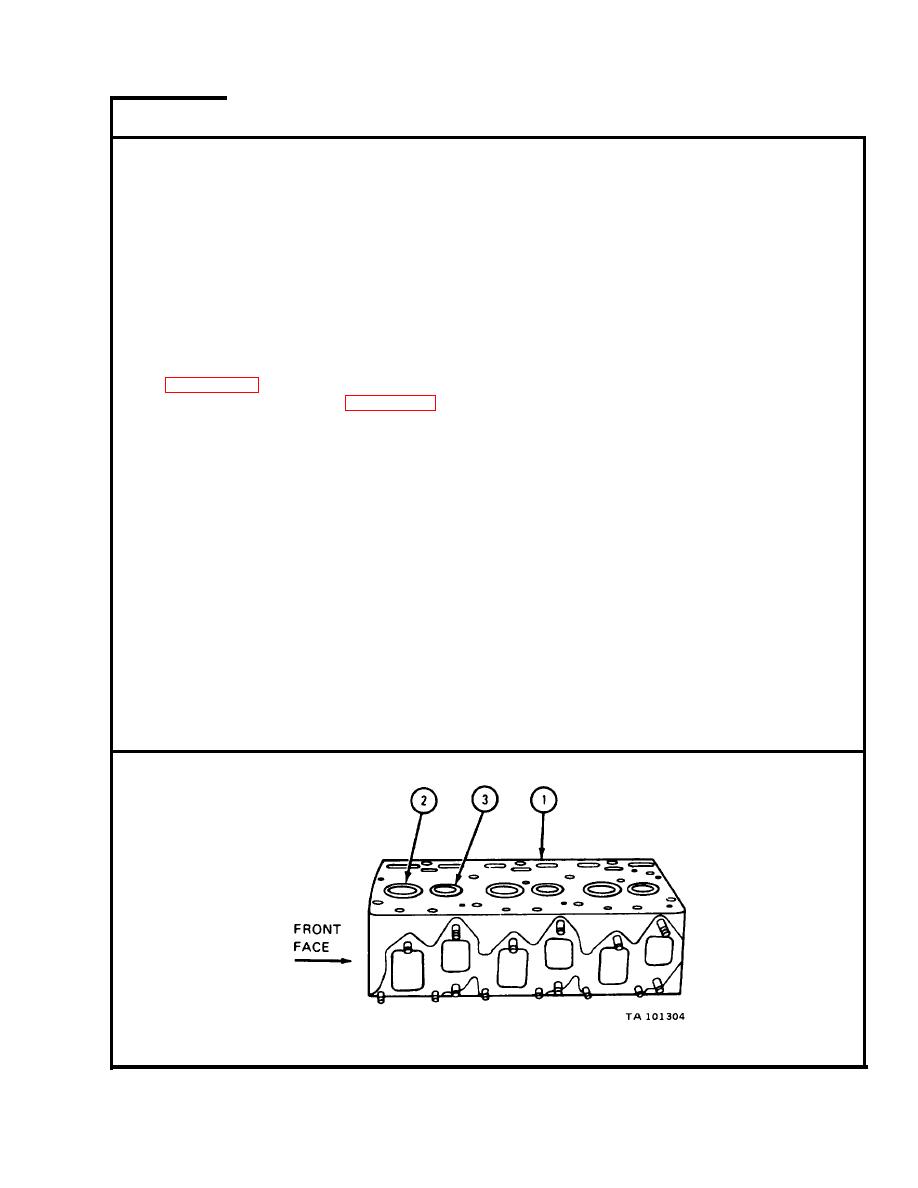
S e n d cylinder head (1) to machine shop.
NOTE
Intake valve seat inserts (2) and exhaust valve seat
i n s e r t s (3) were taken out of cylinder head (1) before
h e a d was sent to machine shop unless valve seat
i n s e r t s need machining.
I n t a k e valve seat inserts (2) are bigger than exhaust
valve seat inserts (3).
I n machine shop,
grind any intake valve seat inserts (2) and any exhaust
2.
v a l v e seat inserts
(3) tagged for machining at a 45 degree angle as shown in
f i g u r e 4-5. Mark
valve seat inserts for replacement if they are worn more
t h a n limits shown
in figure 4-5.
I n machine shop, if cylinder head (1) is tagged for resurfacing, take out
3.
intake valve seat inserts (2) using engine valve seat knockout tool. Tag
i n t a k e valve seat inserts that were not marked to throw away so they can be
put back in the same place.
I n machine shop, if cylinder head (1) is tagged for resurfacing, take out
4.
exhaust valve seat inserts (3) using engine valve seat knockout tool. Tag
e x h a u s t valve seat inserts that were not marked to throw away so they can
be put back in the same place.
I n machine shop, check that intake valve seat counterbores and exhaust valve
5.
s e a t inserts (2 and 3) are not damaged. Mark damaged valve seat counterbores
for machining.
I n machine shop, do frame 10 for intake valve seat counterbores under any
6.
i n t a k e valve se-at inserts (2) just taken out. Do frame 11 again for exhaust
v a l v e seat counterbores under any exhaust valve seat inserts (3) just taken
out.
GO TO FRAME 18
4-227
|
|
Privacy Statement - Press Release - Copyright Information. - Contact Us |