 |
|||
|
|
|||
|
|
|||
| ||||||||||
|
|
 TM 9-2320-366-20-2
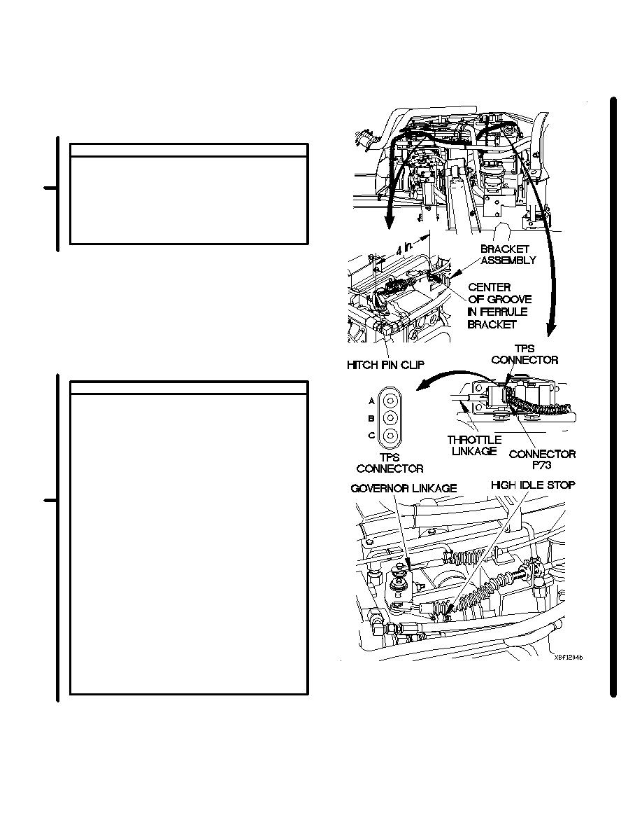
LINKAGE TEST
(1) Raise cab (TM 9-2320-366-10-1).
(2) Verify distance between hitch pin clip on
end of sensor rod and center of cable
groove in ferrule is 4 in. (10 cm).
(3) If distance is not 4 in. (10 cm), adjust
bracket assembly to obtain correct
measurement.
RESISTANCE TEST
(1) Disconnect connector P73 from TPS
connector.
(2) Set multimeter to ohms.
(3) Connect positive (+) probe of multimeter
to TPS terminal A.
(4) Connect negative (-) probe of multimeter to
TPS terminal C and verify multimeter reads
between 9,000-15,000 ohms across
terminals A and C.
(5) Disconnect negative (-) probe of
multimeter from terminal C.
(6) Connect negative (-) probe of multimeter
to TPS terminal B and note record on
multimeter.
(7) Move governor linkage to high idle stop
and record reading on multimeter.
(8) Return governor linkage to low idle stop.
(9) Verify that difference between highest
(high idle) reading and lowest (low idle)
reading is between 4,000 and 6,000
ohms.
(10) Verify that highest (high idle) reading does
not exceed 15,000 ohms.
(11) If resistance readings are not within limits,
replace TPS cable assembly (para 4-16).
Change 1
2-1661
|
|
Privacy Statement - Press Release - Copyright Information. - Contact Us |