 |
|||
|
|
|||
|
Page Title:
THERMAL SWITCH BYPASS PROCEDURE |
|
||
| ||||||||||
|
|
 TM 9-2320-366-20-1
THERMAL SWITCH BYPASS PROCEDURE
(Cont)
WARNING
(10) Cut insulation sleeving 1.5 in. (3.8 cm).
Wear appropriate eye protection when working
(11) Position insulation sleeving on 4 in.
under vehicle due to the possibility of falling
(10.2 cm) wire.
debris. Failure to comply may result in injury to
(12) Install conductor splice on two wires.
personnel.
(13) Install insulation sleeving on conductor
(1) If vehicle is not equipped with connector P81
splice.
continue with step 2 of this fault.
NOTE
(2) If vehicle is equipped with connector P81
Install electrical tape as required.
perform Thermal Switch Bypass Procedure,
see below.
(14) Install conductor splice in convoluted
(3) After performing Thermal Switch Bypass
tubing.
Procedure, attempt to start engine
(15) Lower cab (TM 9-2320-366-10-1).
(TM 9-2320-366-10-1).
(16) Connect batteries (para 7-57).
(4) If engine still does not crank, continue with
step 2 of this fault.
THERMAL SWITCH BYPASS PROCEDURE
NOTE
The tools and materials are required
to perform the thermal switch bypass:
Heater, Gun type, Electrical (Appendix
Tape, Insulation, Electrical (Appendix D,
Item 68)
Splice, Conductor (Item 261, Appendix G)
Insulation Sleeving, Electrical (1.5 in. or
3.8 cm) (Item 28.1, Appendix D)
(1) Disconnect batteries (para 7-57).
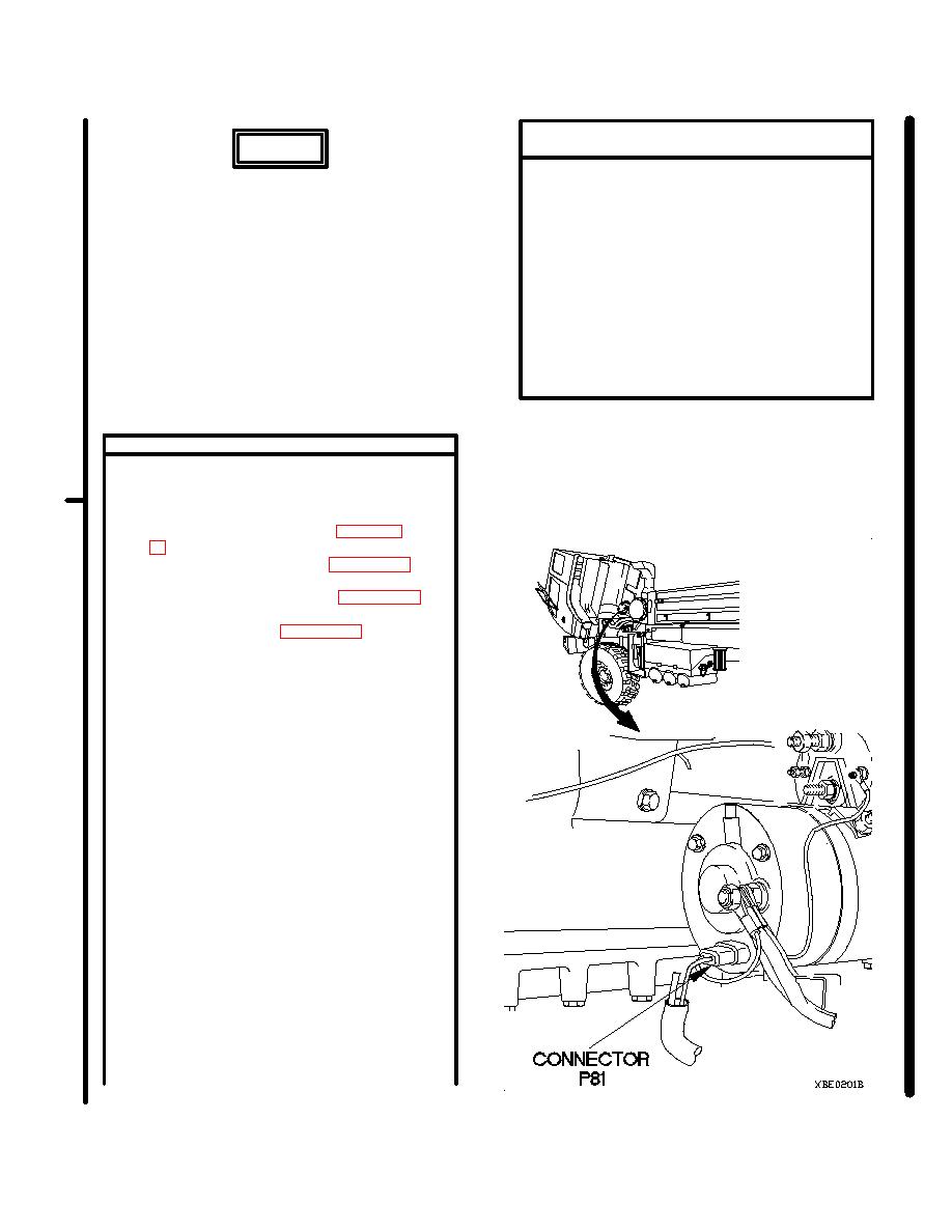
(2) Disconnect connector P81 from thermal
switch connector.
(3) Cut connector P81 from branch of start and
charging cable assembly.
(4) Remove band marker from branch of start
and charging cable assembly.
NOTE
Remove electrical tape as required.
(5) Remove insulation sleeving from convoluted
tubing to body of start and charging cable
assembly.
(6) Remove insulation sleeving from two wires to
body of start and charging cable assembly.
NOTE
Measure wires from body of start and
charging cable assembly.
(7) Cut one wire 3 in. (7.6 cm).
(8) Cut other wire 4 in. (10.2 cm).
(9) Remove 0.38 in. (1 cm) of insulation from two
wires.
Change 1
2-165
|
|
Privacy Statement - Press Release - Copyright Information. - Contact Us |