 |
|||
|
|
|||
|
|
|||
| ||||||||||
|
|
 TM 9--2320-211-34-2-1
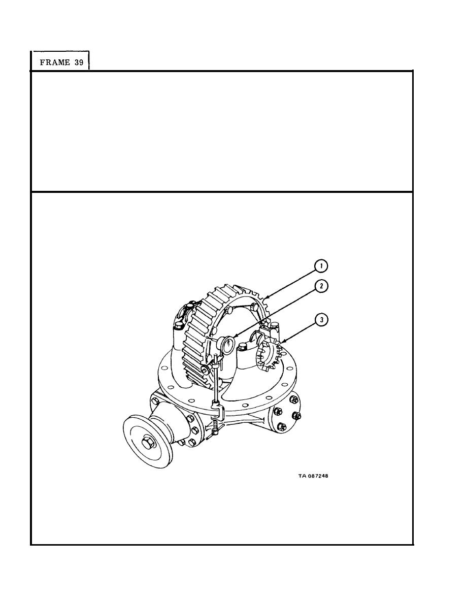
T u r n helical drive gear (1) several times to seat bearings.
1.
P l a c e dial indicator (2) so plunger is against side face of helical drive gear
2.
(1).
P u s h and pull on helical drive gear (1) and check reading on dial indicator (2).
3.
4.
T i g h t e n two adjusting nuts (3) a little at a time. Push and pull on helical
d r i v e gear (1) each time until reading on dial indicator is 0.000 inch.
Turn helical drive gear (1).
U s i n g dial indicator (2), check that runout is
5.
0 . 0 0 8 inch or less.
GO TO FRAME 40
9-80
|
|
Privacy Statement - Press Release - Copyright Information. - Contact Us |