 |
|||
|
|
|||
|
|
|||
| ||||||||||
|
|
 TM 9-2320-211-20-3-2
FRAME 5
1.
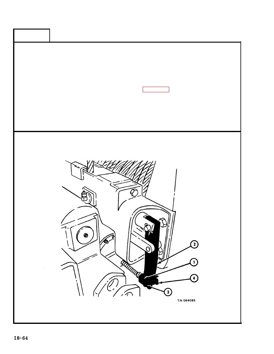
Put yoke (1) in place on adjusting frame lever (2) and aline holes.
2.
Put in yoke pin (3).
Using pliers, put in and bend open ends of cotter pin (4).
3.
NOTE
Follow-on Maintenance Action Required:
1. Replace drive chain. Refer to para 18-8.
2. Tell direct support to replace driven sprocket.
3. Replace driven sprocket shear pin. Refer to
TM 9-2320-211-10.
4. Swing boom to travel position. Refer to
TM 9-2320-211-10.
END OF TASK
|
|
Privacy Statement - Press Release - Copyright Information. - Contact Us |