 |
|||
|
|
|||
|
|
|||
| ||||||||||
|
|
 TM 9-2320-211-20-3-2
FRAME 3
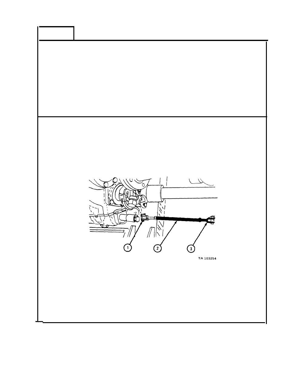
1.
Check alinement of holes for clevis pin (1). Screw control rod (2) in or
out as needed to aline holes for clevis pin. Note number of turns.
NOTE
There must be three or more threads on control rod (2)
screwed into clevis (3).
2.
If control rod was unscrewed in step 1, unscrew it four more turns to
check it. Screw control rod back in four turns. Aline holes for clevis
pin (1).
IF HOLES ARE NOT ALINED, GO TO FRAME 4.
IF HOLES ARE ALINED, GO TO FRAME 5
18-51
|
|
Privacy Statement - Press Release - Copyright Information. - Contact Us |