 |
|||
|
|
|||
|
|
|||
| ||||||||||
|
|
 TM 5-5420-279-23
8
9
3
10
11
686B055
a.
Remove
(1)
Deploy the A-Frame and stabilizer legs.
(2)
Support the weight of the slide frame at section three (1).
(3)
Disconnect the launch system from the vehicle. See operator's manual TM 5-5420-279-10.
(4)
Remove the relax mechanism upper cross member (4). See direct support maintenance
procedure 6-039.
(5)
Remove the stop pads (6) of section two (7 and 2). See unit maintenance procedure 5-080.
(6)
Remove section one (5) of the slide frame and then remove section one (3).
(7)
Check the component parts of Section one.
(8)
Replace parts as required.
(9)
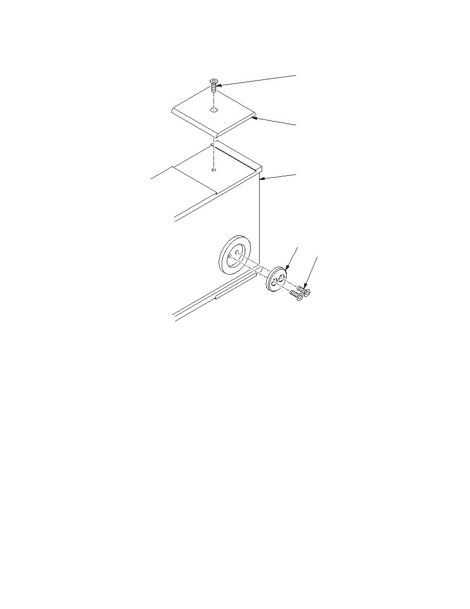
If required remove the screw (8) and remove the wear pad (9), there is another wear pad
fitted to the bottom of section 1 (3).
(10)
Remove the two screws (11) and side wear pad (10), there is another side wear pad fitted
on the opposite side of section 1 (3).
6-104
|
|
Privacy Statement - Press Release - Copyright Information. - Contact Us |