 |
|||
|
|
|||
|
|
|||
| ||||||||||
|
|
 TM 5-5420-279-23
2
7
3
4
5
2
6
NOTE
This procedure may be carried out with the tilt roller assembly fitted to the vehicle or when
the tilt roller assembly is removed from the vehicle.
a.
Remove
(1)
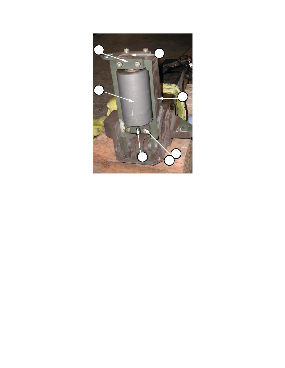
Locate and identify the tilt roller support assembly (1). One is fitted to each side of section
three of the slide frame.
(2)
Locate the roller caps (2), screws (5) and lock washers (6), which secure the roller (3) to
the roller support bracket (4). Discard the lock washers.
(3)
Note the position of the two roller caps.
(4)
Remove the screws (5) and washers (6) securing the roller caps (2).
(5)
Remove the roller caps (2).
(6)
Lift the roller (3) from the roller support bracket (4).
(7)
Examine components for damage and corrosion.
(8)
Examine bolt heads and threads on screws (5) for damage. Check coils of lock washers
are not flattened.
(9)
Replace components as required.
5-277
|
|
Privacy Statement - Press Release - Copyright Information. - Contact Us |