 |
|||
|
|
|||
|
Page Title:
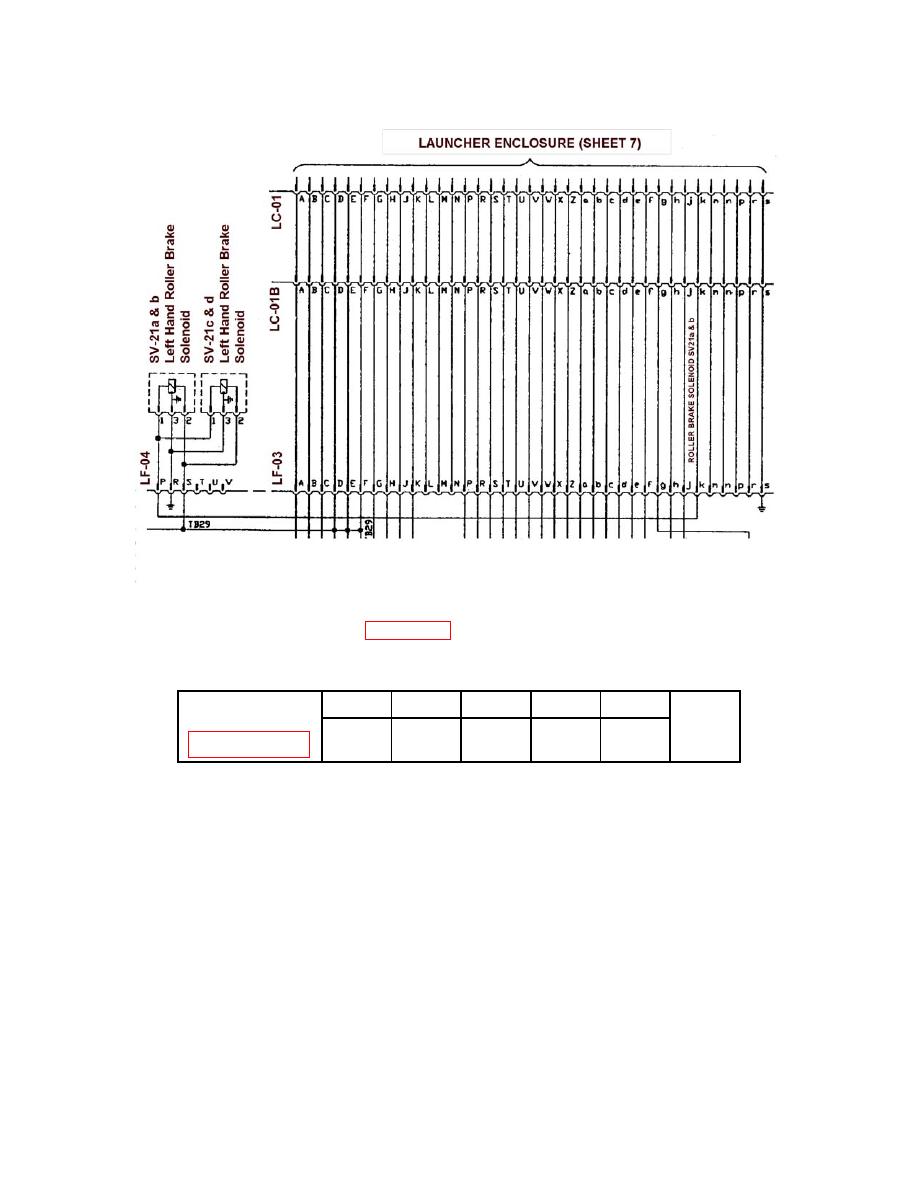
Figure 1 Example of route through an electrical junction box |
|
||
| ||||||||||
|
|
 TM 5-5420-279-23
Figure 1 Example of route through an electrical junction box
(Extract from Appendix G, Annex 4, Page 5, Figure 5)
SV21d 24 Volts
START
From
To
To
To
To
G406-8604 Sheet 5*
END
LC-01
LC-01b
LF-03
LF-04
SV21d
k
k
k
P
1
In the example in Figure 1 the power starts at the Launcher Controller plug LC-01 pin k (lower
case letter) runs through a harness via bulkhead at LC-01B pin k and connects to the Lower A-
Frame junction Box at plug LF-03 pin k, goes through the Lower A-Frame junction Box and exits
at plug LF-04 pin P (upper case letter). It terminates at the consumer unit SV21d at pin 1.
A typical example of the layout of a connector receptacle is shown in Figure 2, it shows the
lettering convention used. Upper case letters are used to label pins, with lower case letters used if
more than 26 pin labels are required.
3-56
|
|
Privacy Statement - Press Release - Copyright Information. - Contact Us |