 |
|||
|
|
|||
|
|
|||
| ||||||||||
|
|
 TM 5-5420-279-23
FUNCTION
SELECT
TILT
ROLLER
CARRIAGE
STOW
EMPTY
HIGH
BANK
BEAM
A FRAME
FARBANK
MODE
BEAM
STOW
=LEVEK
L
TOP
BRIDGE
DRIVE
RAISE
SEAT
SELECT
ANGLE
ARTIC
BAN
WINCH
LIFT
LOW
EMERGENCY STOP
POWER
BANK
ROLLER
BRIGHT
OFF
FAULT
BRAKE
OFF
ON
DIM
OFF
ROLLER BRAKE
PUSH TO STOP - TWIST TO RESET
686A356
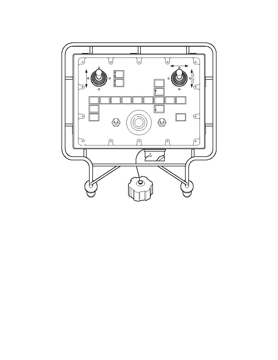
Fig 1.10 Launch Chest Pack
d.
The display screen shows a series of illuminated captions with text legends to indicate
which function is in operation at the time and previously selected options (e.g. High
Beam/Level/Low Beam option). The screen is sunlight readable and contains a dimming facility
for night deployments.
e.
Warning lights in the form of monitored indicators, showing critical and non-critical faults,
are also displayed on the screen to prompt the operator to further investigate malfunctions on the
mimic panel within the electrical control cabinet.
f.
The voltage control circuitry provides +/- 10 V dc to the joystick. All other functions are
24 V dc directly powered from the electrical control cabinet.
1-10-30 Bridging Modules
Two ramp modules and end beams, five parallel modules and 20 approach ramps are pinned and
shoot bolted together to form the bridge span. Two extra ramp modules, two end beams and 20
approach ramps are located on an additional trailer to deploy two 65 ft 6 in (20 m) bridges instead
of one 131 ft (40 m) bridge if required.
1-21
|
|
Privacy Statement - Press Release - Copyright Information. - Contact Us |