 |
|||
|
|
|||
|
|
|||
| ||||||||||
|
|
 TM 5-5420-279-23
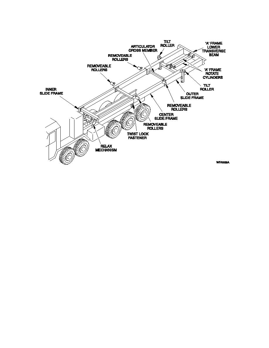
Fig 1.6 Slide Frame
1-10-21 Relax Mechanism
a.
The relax mechanism forms part of the attachment of the inner slide frame to the vehicle
chassis. It isolates movement of the slide frame during launch beam and bridge construction,
which tend to cant the A-Frame forward or rearward out of vertical. Isolation of the slide frame
movement prevents a rearward pull on the vehicle towards the gap and possible damage to the
crane stabilizer legs. The mechanism is unlocked by manual operation of shoot bolts and allows a
controlled sliding movement of 3 in (80 mm) if the A-Frame tends to cant towards the gap and 1
in (25 mm) if it tends to cant away from the gap, dependent on site and build conditions.
b.
Four hydraulic cylinders are used to re-set the relax mechanism to its neutral position on
completion of bridging operations. The cylinders, acting in pairs (each pair controlling 3 in (80
mm) and 1 in (25 mm) movement), are actuated from the control box on the right side of the
launcher vehicle to the rear of the crane. Movement of the cylinders re-aligns the holes to install
the shoot bolts, locking the relax mechanism back in its neutral setting ready for the next
deployment. Limit switches, operated by the shoot bolts, prevent operation of the launch chest
pack controls until the relax mechanism is unlocked for operation.
1-10-22 Tilt Rollers
The two tilt rollers maintain tension on the carriage slings during bridging operations. They are
operated by hydraulic cylinders fitted to the slide frame and adjust the bridge angle to
compensate for the launch beam angle created by varying bank heights.
1-15
|
|
Privacy Statement - Press Release - Copyright Information. - Contact Us |