 |
|||
|
|
|||
|
|
|||
| ||||||||||
|
|
 TM 5-5420-279-23
locally by its integral lever or remotely using integral proportional control valves. One slice is used
to operate the raise and lower of the upper A-Frame transverse beam when changing between
launch beam and bridging module sequences and the other controls the inclination of the rollers
during initial bridge deployment. The slices of the control valves are operated by button switch
selection on the interface cabinet or by valve handles.
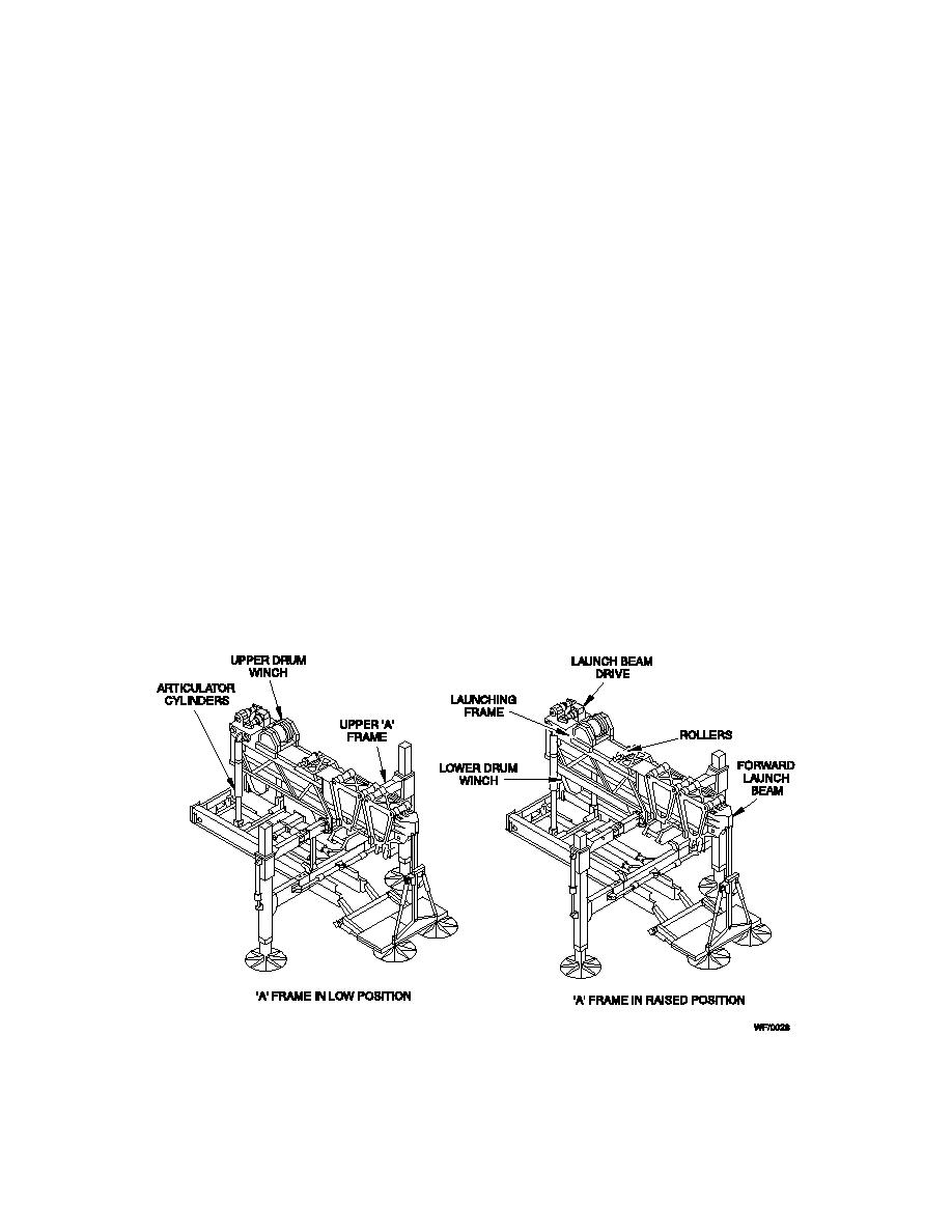
1-10-14 Launch Frame
a.
The launch frame is a steel framework through which the launch beam passes during
launch beam deployment. It is attached at its forward end to the upper A-Frame transverse beam
via a pivot. When the upper A-Frame transverse beam is in its lower position, the rear end of the
framework is supported by the launch frame articulating hydraulic cylinders. Once beam
deployment is complete, the lower end of the articulating hydraulic cylinders are disconnected
and moved by retraction of the articulator stowing cylinders to a stowed position to give clearance
for the bridging modules.
b.
The forward launch beam is retained in the launch frame after beam retrieval, ready for the
next beam deployment.
c.
Mounted on the framework are various roller assemblies, two drum winches, the launch
beam drive unit and launch valves.
d.
At the upper part of the launch frame is a cam-operated launch beam stop to prevent over
deployment of a launch beam if no following beam is attached. The launch beam stop is lifted by
a roller on the following beam, which raises the stop and allows forward motion of the launch
beam.
Fig 1.5 Launch Frame
1-12
|
|
Privacy Statement - Press Release - Copyright Information. - Contact Us |