 |
|||
|
|
|||
|
|
|||
| ||||||||||
|
|
 TM9-2920-225-34
FRAME 3
CAUTION
Do not use a battery or test lamp to make a continuity
test. Reverse battey connection will burn out diodes
instantly .
NOTE
On ohmmeters that use one 1 1/2-volt dry cell, low
resistance readings will be approximately 20 to 30
ohms. On ohmmeters that use a 3-volt dry cell,
low resistance readings will be approximately 10 to 15
ohms.
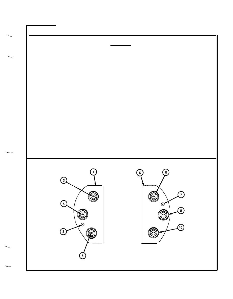
Positive rectifier has a coating of epoxy for insulation.
1.
Check positive rectifier (1) for resistance using a multimeter. Touch positive
test probe to checkpoint one (2) and negative test probe to each of three
rectifiers (3, 4, and 5), ohmmeter must show low resistance when negative
test probe is touched to each rectifier.
Check negative rectifier (6) for resistance using a multimeter. Touch
2.
negative test probe to checkpoint two (7) and positive test probe to each of
three rectifiers (8, 9, and 10). Ohmmeter must show low resistance when
positive test probe is touched to each rectifier.
Get new parts for those which do not show low resistance.
3.
END OF TASK
TA103570
2-69
|
|
Privacy Statement - Press Release - Copyright Information. - Contact Us |
