 |
|||
|
|
|||
|
|
|||
| ||||||||||
|
|
 TM
9-2815-210-34-2-2
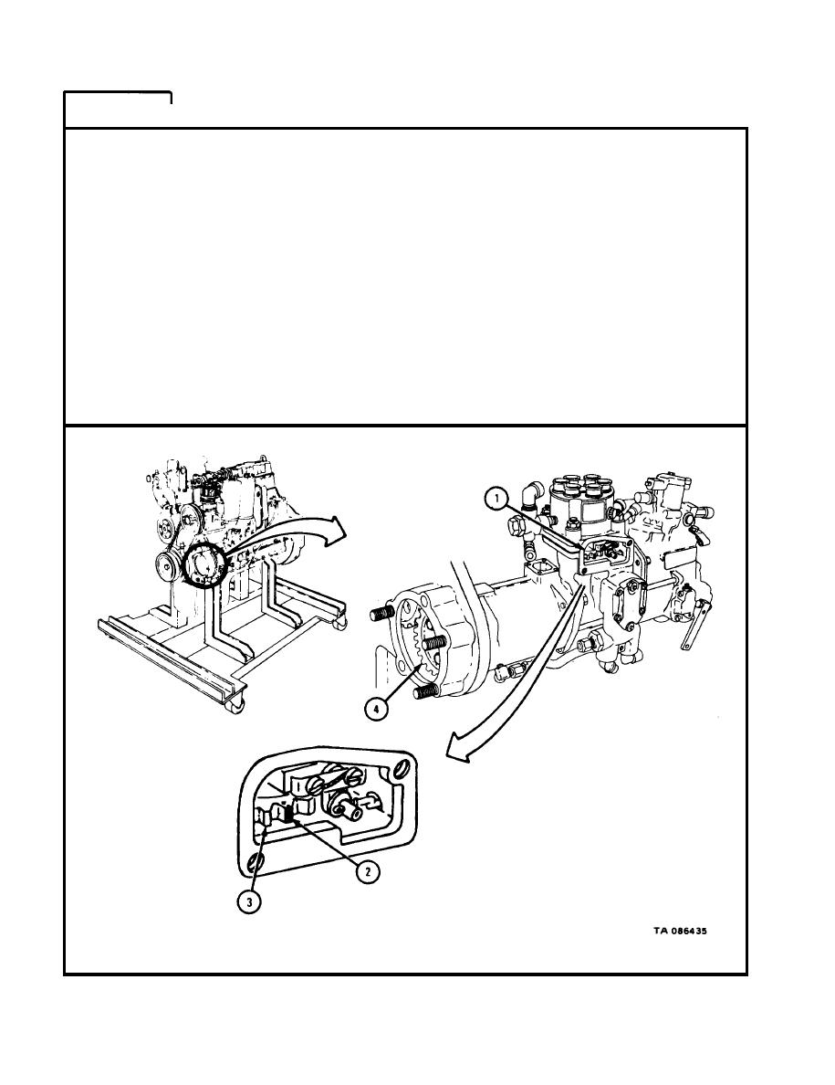
FRAME
13
NOTE
F u e l injection pump shown is for engines LD-465-1,
L D - 4 6 5 - 1 C , and LDT-465-1C. The procedure is the same
for engines LDS-465-1, LDS-465-1A, and LDS-465-2.
1.
C h e c k that proper timing mark on crankshaft damper and pulley assembly is
l i n e d up with pointer on timing gear cover as shown in frame 1. Check that
c y l i n d e r number one intake and exhaust valves are closed as shown in frame
2.
L o o k in window (1) and check that marked tooth (2) on gear (3) can be seen.
2.
I f marked tooth (2) on gear (3) cannot be seen through window (1), pump
3.
t i m i n g is not correct. T a k e off fuel pump drive gear (4). Refer to Part 1,
p a r a 3 - 1 0 . T h e n set and check pump timing. Refer to frame 6 and frames
11 through 13.
GO TO FRAME 14
5-184
|
|
Privacy Statement - Press Release - Copyright Information. - Contact Us |
