 |
|||
|
|
|||
|
|
|||
| ||||||||||
|
|
 TM 9-2815-210-34-2-2
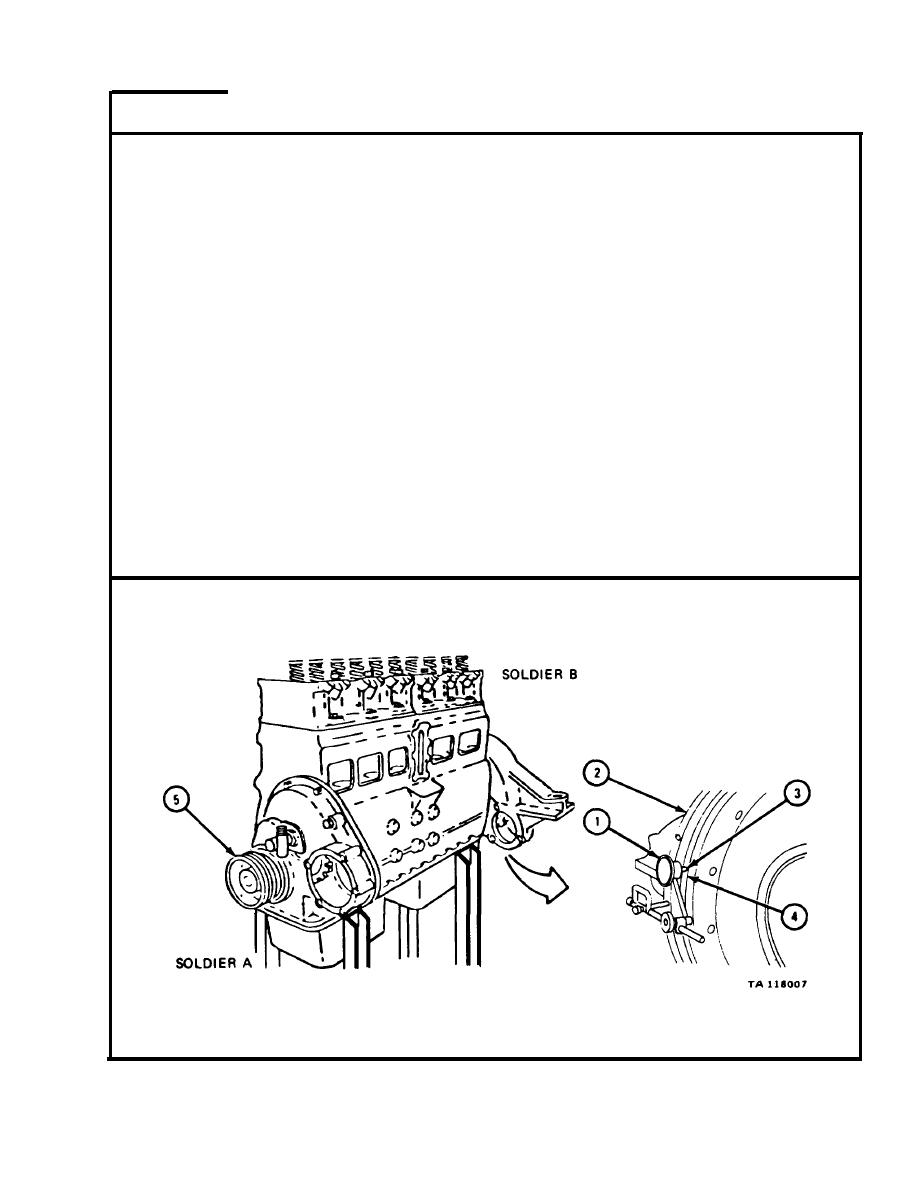
FRAME 4
NOTE
When checking flywheel rim (4) runout, push flywheel
f o r w a r d as far as it will go. Hold forward pressure on
f l y w h e e l while turning crankshaft pulley (5).
1.
Soldier A
M o u n t dial indicator (1) on flywheel housing (2) so indicator
p o i n t e r (3) rests on flywheel rim (4) as shown. Set dial indi-
c a t o r to zero.
Soldier B
2.
U s i n g engine barring tool, turn crankshaft pulley (5) slowly
to the right until soldier A tells you to stop.
Soldier A
3.
R e a d dial indicator (1) as soldier B turns crankshaft pulley (5).
When dial indicator is at the highest reading, tell soldier B to
s t o p . S e t dial indicator to zero.
Soldier B
4.
W h e n soldier A is ready, turn crankshaft pulley (5) slowly one
f u l l turn to the right.
NOTE
Dial indicator (1) will now read total flywheel runout. Fly-
wheel runout must not be more than 0.008 inch.
Soldier A
5.
R e a d dial indicator (1) as soldier B turns crankshaft pulley (5).
GO TO FRAME 5
5-79
|
|
Privacy Statement - Press Release - Copyright Information. - Contact Us |
