 |
|||
|
|
|||
|
|
|||
| ||||||||||
|
|
 TM
9-2815-210-34-2-2
FRAME 3
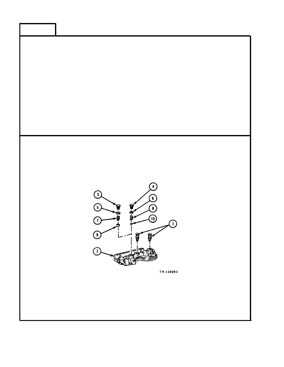
1.
T a k e two bleeder valves (1) out of fuel filter head (2).
NOTE
Relief valve can have valve, spring, and 3/4-inch
hexagon head plug or ball, spring, and 1-inch
h e x a g o n p l u g . R e l i e f valve assemblies cannot be
s w i t c h e d in fuel filter heads and individual parts
o f relief valve assemblies cannot be switched.
E a r l y model fuel filter heads have two bleeder
v a l v e s . Late model fuel filter heads have only one
b l e e d e r valve in middle of head.
2.
T a k e out relief valve plug (3 or 4), preformed packing (5) or gasket (6),
s p r i n g (7 or 8), and relief valve (9) or ball (10) from fuel filter head (2).
3.
Throw away preformed packing (5) or gasket (6).
GO TO FRAME 4
4-328
|
|
Privacy Statement - Press Release - Copyright Information. - Contact Us |
