 |
|||
|
|
|||
|
|
|||
| ||||||||||
|
|
 TM
9-2815-210-34-2-2
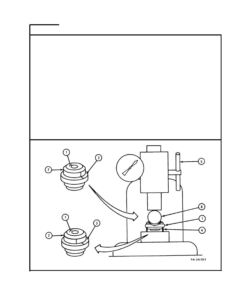
FRAME
2
NOTE
D o this frame for all six valve rotors (1) in cylinder head
assembly.
D r a w a chalk mark across inner section (2) and outer section (3) of valve
1.
rotor (1) as shown.
2.
P u t rotor (1) in a container of clean engine oil.
P u t short steel sleeve (4) on platform of spring tester (5) as
3.
shown.
T a k e rotor (1) out of container of oil. Let excess oil drip off. Put rotor (1)
4.
o n sleeve (4) with valve spring seat side down as shown.
P u t 3/4-inch hardened steel ball (6) on top of rotor (1) as shown.
5.
Work spring tester (5) to put a load of 260 pounds on ball (6) on top of valve
6.
r o t o r ( 1 ) . Then let up load to 110 pounds.
Do step 6 again 25 to 30 times. C h e c k that marks on inner section (2) and
7.
o u t e r section (3) of valve rotor (1) move apart as shown. If marks do not
m o v e apart, throw away valve rotor and get a new one.
END OF TASK
4-251
|
|
Privacy Statement - Press Release - Copyright Information. - Contact Us |
