 |
|||
|
|
|||
|
|
|||
| ||||||||||
|
|
 TM 9-2815-210-34-2-2
FRAME
7
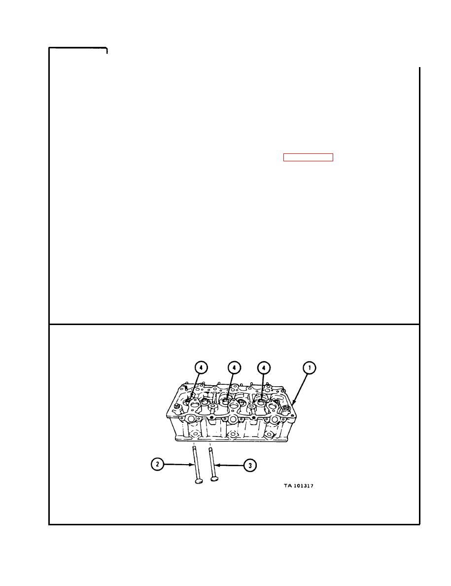
NOTE
T h i s frame is for early model cylinder heads (1). Early
m o d e l cylinder heads used intake valves (2) different
f r o m the ones used on late model cylinder heads.
E a r l y model intake valves (2) have a dull shot peened
f i n i s h . L a t e model intake valves have a shiny chrome
plated finish.
Readings must be within limits given in tables 4-53 and
4 - 5 4 . The letter L shows a loose fit. I f readings are
not within given limits, throw away part and get a new
o n e . Be sure to use limits which apply to the type of
i n t a k e valve (2) you are working on.
I n t a k e valves (2) and exhaust valves (3) were tagged
s o fit of each valve can be measured in valve guide (4)
i t was removed from.
M e a s u r e and note outside diameter of stem of three intake valves (2).
1.
M e a s u r e and note inside diameter of three intake valve guides (4) 1/8 to 1/4
2.
i n c h from each end of guide. I f diameter is different at each end, note
biggest diameter.
Measure fit of stem of each i n t a k e valve (2) in its intake valve guide (4).
3.
Do this for all three intake v a l v e s and intake valve guides.
D o steps 1, 2, and 3 again f o r t h r e e e x h a u s t v a l v e s ( 3 ) .
4.
END OF TASK
4-245
|
|
Privacy Statement - Press Release - Copyright Information. - Contact Us |
