 |
|||
|
|
|||
|
Page Title:
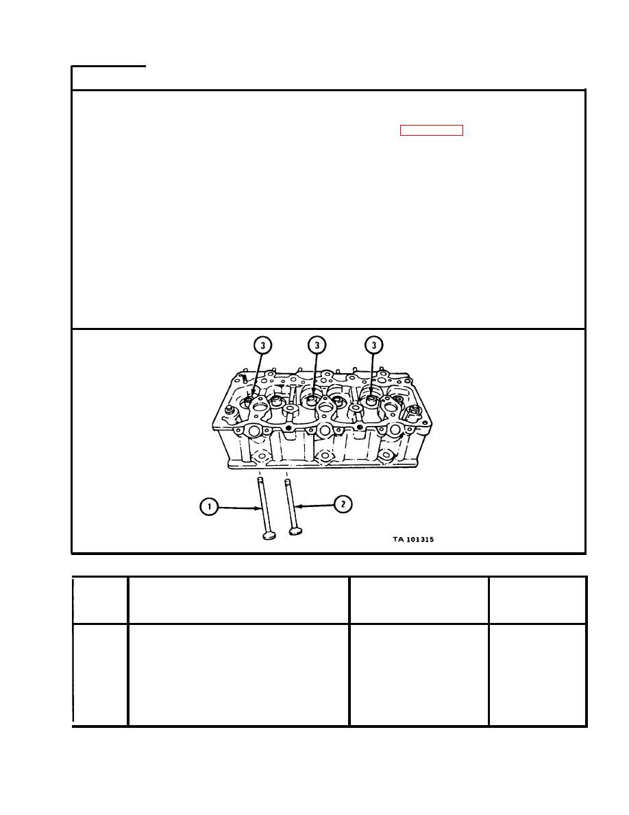
Table 4-51. Intake Valves and Guides Wear Limits |
|
||
| ||||||||||
|
|
 TM
9-2815-210-34-2-2
FRAME 5
NOTE
Readings must be within limits given in table 4-51.
The letter L shows a loose fit. I f readings are not
within given limits, throw away part and get a new
one.
I n t a k e valves (1) and exhaust valves (2) were
t a g g e d so the fit of each valve stem can be measured
i n valve guide it was taken from.
Measure a n d note outside diameter of stem of three intake valves (1).
1.
Measure a n d note inside diameter of three intake valve guides (3) 1/8 to 1/4
2.
i n c h from each end of guide. I f diameter is different at each end of guide,
n o t e biggest diameter.
M e a s u r e fit of stem of each intake valve (1) in its intake valve guide (3). Do
3.
t h i s for all three intake valves and intake valve guides.
GO TO FRAME 6
Intake Valves and Guides Wear Limits
Size and Fit
Wear Limit
Index
of New Parts
(inches)
(inches)
Item /Point of Measurement
Number
I n t a k e valve stem outside
1
0.4363
diameter
0 . 4 3 6 8 to 0.4373
I n t a k e valve guide inside
3
0.4420
diameter
0 . 4 3 8 8 to 0.4394
1 and 3
Fit of intake valve stem
i n intake valve guide
0.0015L to 0.0026L
0.0057L
|
|
Privacy Statement - Press Release - Copyright Information. - Contact Us |
