 |
|||
|
|
|||
|
|
|||
| ||||||||||
|
|
 TM 9-2815-210-34-2-2
FRAME 11
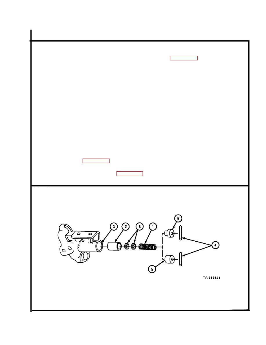
NOTE
Readings must be within limits given in table 4-31. The
letter L shows a loose fit. If readings are not within
given limits, throw away part and get anew one.
Relief valve spring (1) and plunger (2) come together
in a kit. Kit also has a new retaining pin (4), one of
two types of spring retainer (5), and shims (6). If any
of these parts are damaged, all should be changed. If
kit has two plungers, longer one is for this pump.
If you get a new parts kit, save all shims (6) in the kit,
even if pump had no shims. Shims will be used later
for pump test and adjustment.
Measure free length of relief valve spring (1).
1.
Measure l o a d needed to squeeze relief valve spring (1) down to 2.100 inches.
2.
Measure m a x i m u m solid height of relief valve spring (1).
3.
Measure o u t s i d e diameter of relief valve plunger (2).
4.
I f reading is not within
Measure i n s i d e diameter of relief valve bore (3).
5.
limits given in table 4-31, get a new oil pump.
M e a s u r e fit of relief valve plunger (2) in relief valve bore (3). If reading
6.
is not within limits given in table 4-31, get a new oil pump.
GO TO FRAME 12
4-169
|
|
Privacy Statement - Press Release - Copyright Information. - Contact Us |
