 |
|||
|
|
|||
|
|
|||
| ||||||||||
|
|
 TM 9-2815-210-34-2-2
FRAME 10
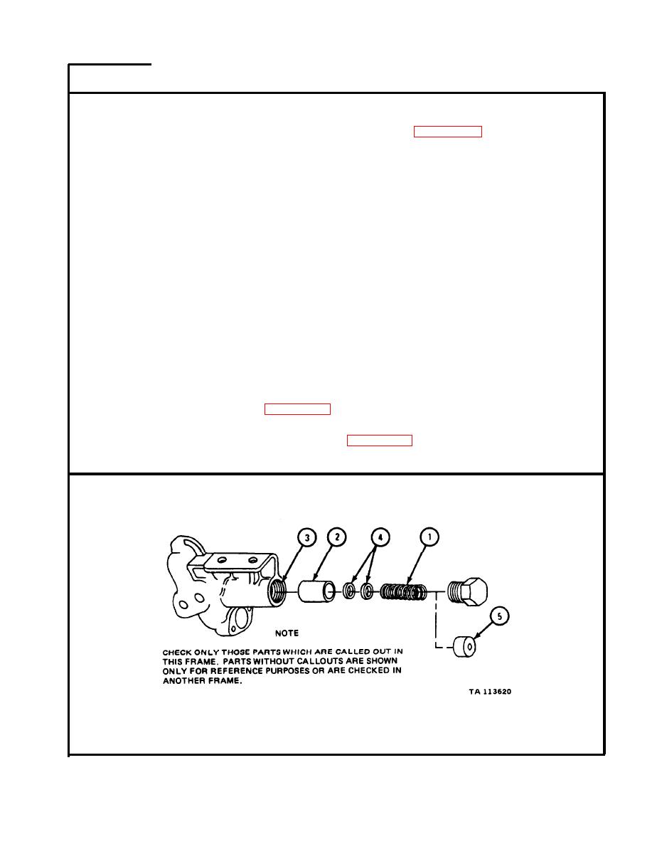
NOTE
Readings must be within limits given in table 4-30. The
letter L shows a loose fit. If readings are not within given
limits, throw away part and get a new one.
Shims (4) are used .to adjust pressure relief valve. The
number of shims may differ from pump to pump. Some
pumps may have no shims.
Pressure relief valve spring (1) comes in a parts kit
which has new shims (4). If you get a new parts kit,
save all the shims even if pump had no shims. Shims
will be used later during pump test and adjustment.
Parts kit also contains a new plunger (2) and a type of
spring retainer (5) with no threads. This plunger and
spring retainer are for late model pumps and should not
be used on early model pumps.
Measure free length of relief valve spring (1). Measure load needed to
1.
s q u e e z e relief valve spring (1) to 2.100 inches. Measure maximum solid
height of relief valve spring (1).
2.
M e a s u r e outside diameter of pressure relief valve plunger (2).
3.
M e a s u r e inside diameter of pressure relief valve bore (3). If reading is
not within limits given in table 4-30, get a new oil pump.
M e a s u r e fit of relief valve plunger (2) in pressure relief valve bore (3).
4.
If reading is not within limits given in table 4-30, get a new oil pump.
GO TO FRAME 11
4-167
|
|
Privacy Statement - Press Release - Copyright Information. - Contact Us |
