 |
|||
|
|
|||
|
|
|||
| ||||||||||
|
|
 TM 9-2520-246-34-1
d.
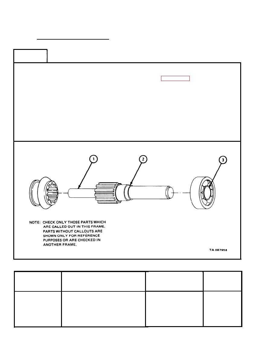
Shouldered Shaft Assembly.
FRAME 1
NOTE
Readings must be within limits given in table 2-65. The
letter L indicates a loose fit and the letter T indicates a
tight fit. If readings are not within given limits, throw
away part and get a new one.
1.
Measure shouldered shaft diameter (1).
2.
Measure shouldered shaft diameter (2).
Measure inside diameter of bearing (3).
3.
Measure fit of bearing (3) on shouldered shaft diameter (2).
4.
END OF TASK
Table 2-65.
Shouldered Shaft Assembly Wear Limits
Size and Fit
Wear Limit
of New Parts
Index Number
(inches)
Item/Point of Measurement
(inches)
None
1
Shaft outside of diameter
0.6230 to 0.6235
None
2
Shaft outside diameter
0.9843 to 0.9847
None
3
Bearing inside diameter
0.9840
None
Fit of bearing on shaft
0.003T to 0.007T
3 and 2
2-320
|
|
Privacy Statement - Press Release - Copyright Information. - Contact Us |
