 |
|||
|
|
|||
|
Page Title:
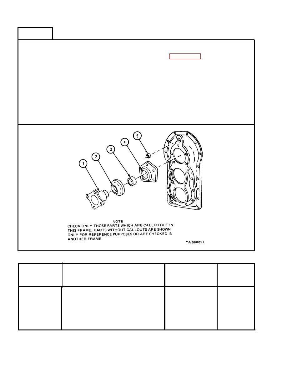
Table 2-55. Input Shaft Cover Wear Limits |
|
||
| ||||||||||
|
|
 TM 9-2520-246-34-1
FRAME 8
NOTE
Readings must be within limits given in table 2-55. If read-
ings are not within given limits, throw away part and get a
new one.
1.
Measure flange outside diameter (1).
2.
Measure deflector inside diameter (2).
3.
Measure oil seal outside diameter (3).
Measure input shaft cover bore (4).
4.
Measure oil seal outside diameter (5).
5.
GO TO FRAME 9
Table 2-55.
Input Shaft Cover Wear Limits
Size and Fit
Wear Limit
of New Parts
Index Number
Item/Point of Measurement
(inches)
(inches)
1
Input shaft flange outside diameter
2.4016 to 2.4056
2.4010
2
Deflector inside diameter
2.3956 to 2.3996
None
3
Oil seal outside diameter
3.3524 to 3.3563
None
4
Input shaft cover bore
3.3465 to 3.3485
3.3495
5
1.5000 to 1.5039
Oil seal outside diameter
None
2-216
|
|
Privacy Statement - Press Release - Copyright Information. - Contact Us |
