 |
|||
|
|
|||
|
Page Title:
Table 2-21. Countershaft Assembly Fits and Tolerances |
|
||
| ||||||||||
|
|
 TM 9-2520-246-34-1
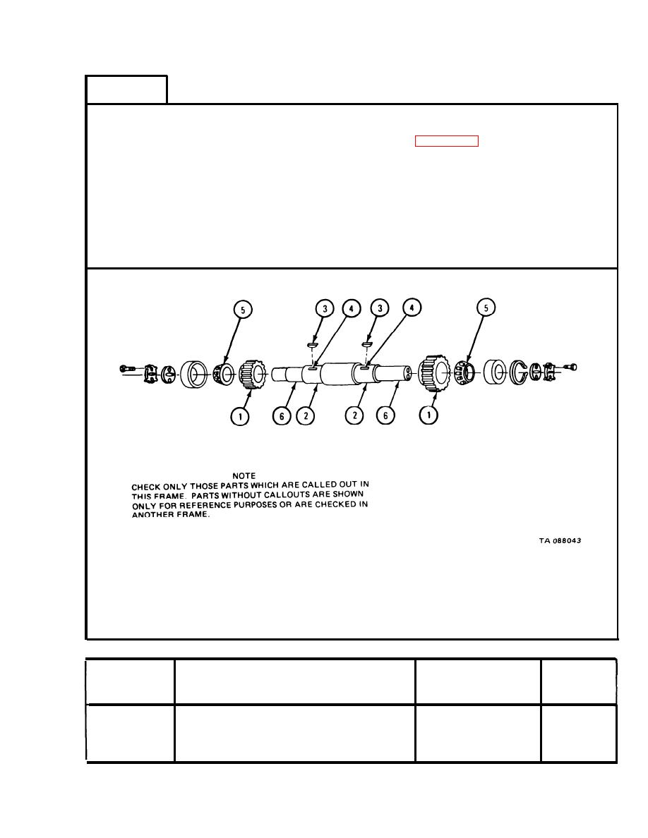
FRAME 3
NOTE
Readings must be within limits given in table 2-21. The
letter L indicates a loose fit and the letter T indicates a
tight fit. If readings are not within given limits, throw
away part and get a new one.
1.
Measure fit of two gears (1) on two countershaft gear surfaces (2).
2.
Measure fit of two keys (3) in two countershaft keyways (4).
3.
Measure fit of two bearings (5) on two countershaft bearing surfaces (6).
END OF TASK
Countershaft Assembly Fits and Tolerances
Table 2-21.
Size and Fit
of New Parts
Wear Limit
Index Number
Item/Point of Measurement
(inches)
(inches)
Fit of gear on shaft
1 and 2
0.0005T to 0.0025T
0.0010L
0.0010L to 0.0020T
Fit of key in keyway
.0030L
3 and 4
Fit of bearing on shaft
0.0005T to 0.0015T
None
5 and 6
2-181
|
|
Privacy Statement - Press Release - Copyright Information. - Contact Us |
