 |
|||
|
|
|||
|
|
|||
| ||||||||||
|
|
 TM 9-2520-246-34-1
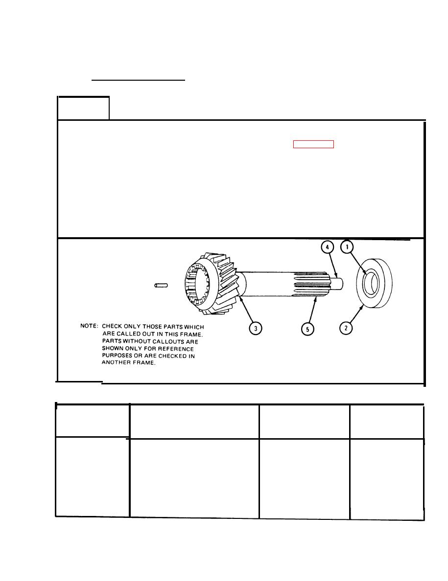
2-8. WEAR LIMIT INSPECTION. The following paragraphs give instructions for
checking the minimum and maximum wear limits for each subassembly to which a part
or parts may be worn before a new part is needed.
Input Shaft Assembly.
a.
FRAME 1
NOTE
Readings must be within limits given in table 2-3. If
readings are not within given limits, throw away part
and get a new one.
1.
Measure bearing inside diameter (1) and out side diameter (2).
2.
Measure bearing journal diameter (3).
3.
Measure pilot diameter (4).
4.
Measure width of splines (5).
GO TO FRAME 2
Table 2-3.
Input Shaft Assembly Wear Limits
Size and Fit
of New Parts
Wear Limit
Index Number
Item/Point of Measurement
(inches)
(inches)
1
Bearing inside diameter
1.5748 to 1.5753
None
2
Bearing outside diameter
3.5427 to 3.5433
None
3
Bearing journal diameter
1.5748 to 1.5752
None
4
Pilot diameter
0.7465 to 0.7475
0.020
5
Spline width
0.229 to 0.231
0.015
2-49
|
|
Privacy Statement - Press Release - Copyright Information. - Contact Us |
