 |
|||
|
|
|||
|
|
|||
| ||||||||||
|
|
 TM 9-2320-366-20-3
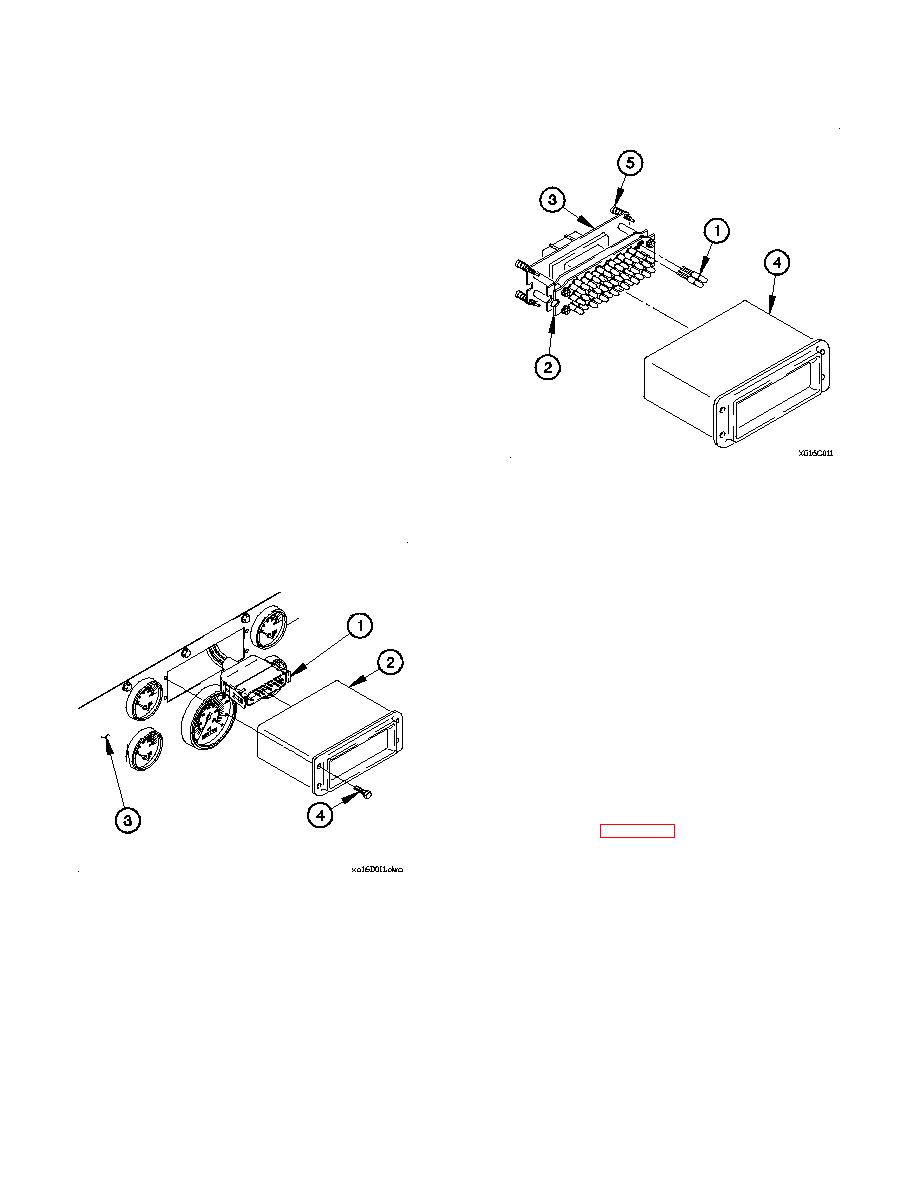
c. Assembly.
NOTE
Left turn indicator, right turn indicator, and
high beam indicator are 12 vdc lamps. All
other lamps are 24 vdc.
(1) Install replacement lamp(s) (1) in printed circuit board
(2).
(2) Install lamp mounting panel (3) in lighted indicator
display housing (4).
(3) Tighten four captive screws (5) in lamp mounting panel
(3).
d. Installation.
(1) Connect connector PX7 (1) to lighted indicator display
(2).
(2) Position lighted indicator display (2) in instrument panel
assembly (3) with four screws (4).
(3) Tighten four screws (4) to 9 lb-in. (1 Nm).
e. Follow-On Maintenance.
(1) Connect batteries (para 7-57).
(2) Check operation of lighted indicator display (TM 9-2320-
366-10-1).
End of Task.
7-111
|
|
Privacy Statement - Press Release - Copyright Information. - Contact Us |
