 |
|||
|
|
|||
|
|
|||
| ||||||||||
|
|
 TM 9-2320-366-20-2
CAUTION
Use care when testing electrical connectors.
Do not damage connector pins or sockets
with multimeter probes. Failure to comply
may result in damage to equipment.
NOTE
Inspect connector pins/sockets for damage,
corrosion, and serviceability. Check that
connector pins are not pushed back and
are capable of making good contact.
CONTINUITY TEST
(1)
Disconnect batteries (para 7-57).
(2)
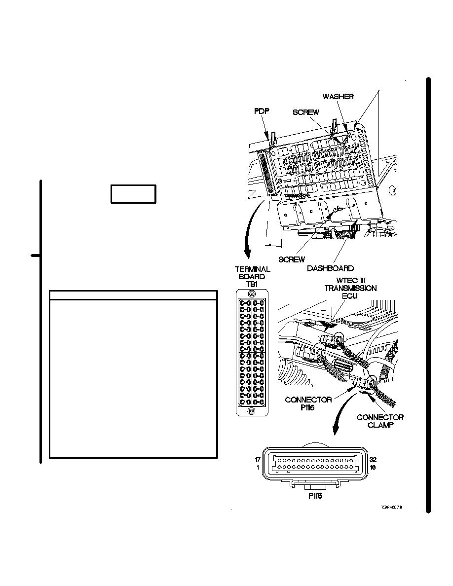
Remove PDP cover (para 16-2).
(3)
Remove three screws from PDP.
(4)
Remove three screws and washers from PDP.
(5)
Lift PDP outward to gain access.
(6)
Set multimeter to ohms.
(7)
Connect positive (+) probe of multimeter to
connector P116 socket 4.
(8)
Connect negative (-) probe of multimeter to
terminal board TB1 position 60 and note
reading on multimeter.
(9)
If continuity is not present, Repair wire
146 from connector P116 socket 4
to terminal board TB1 position 60
(para 2-45) or replace WTEC III dashboard
cable assembly (para 7-11).
(10)
Connect connector P116 to WTEC III ECU.
(11)
Connect connector clamp to connector P116.
(12)
Install kick panel (para 16-3).
Change 1
2-1822.25
|
|
Privacy Statement - Press Release - Copyright Information. - Contact Us |
