 |
|||
|
|
|||
|
|
|||
| ||||||||||
|
|
 TM 9-2320-366-20-2
WARNING
Remove rings, bracelets, watches, necklaces,
and any other jewelry before working around
vehicle. Jewelry can catch on equipment and
cause injury or short across electrical circuits
and cause severe burns or electrical shock.
CAUTION
Use care when testing electrical connectors.
Do not damage connector pins or sockets
with multimeter probes. Failure to comply
may result in damage to equipment.
NOTE
Inspect connector pins/sockets for damage,
corrosion, and serviceability. Check that
connector pins are not pushed back and
are capable of making good contact.
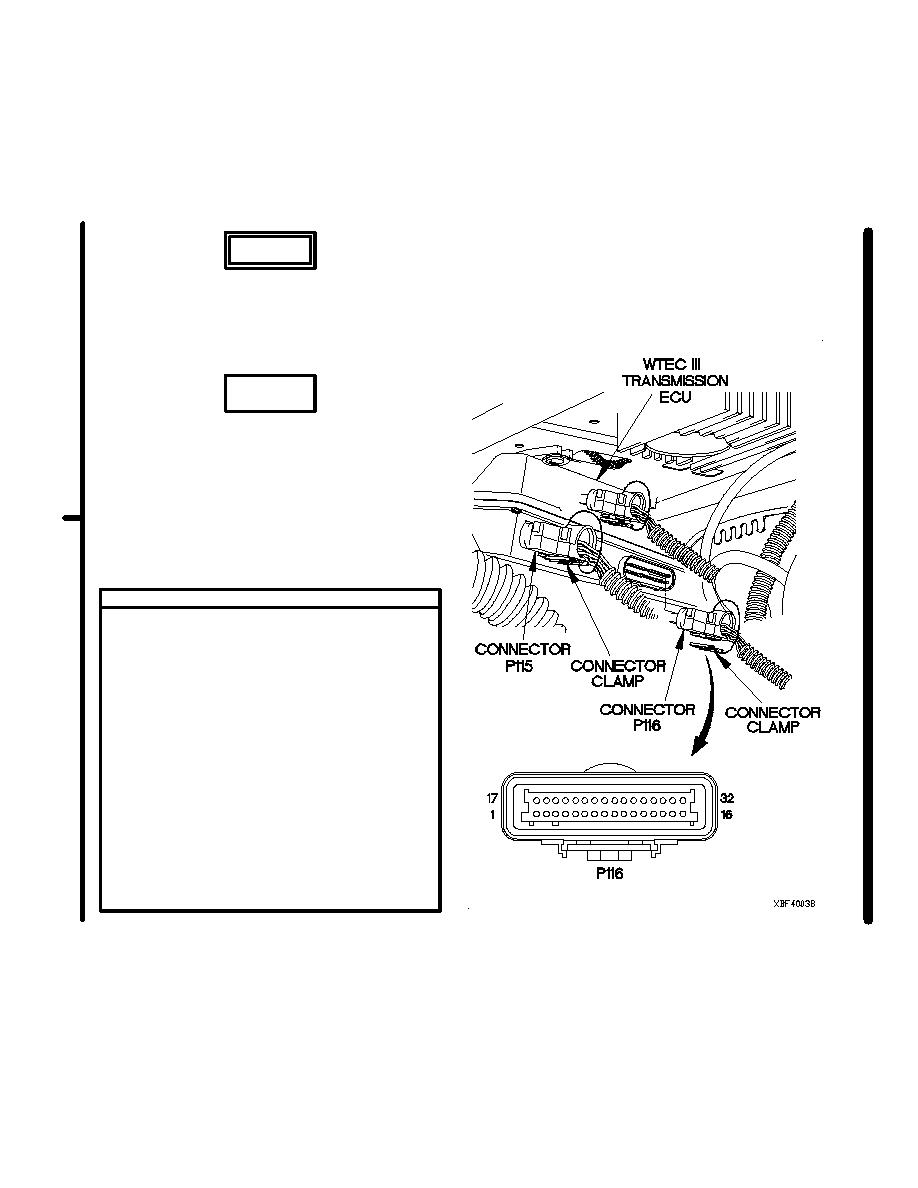
VOLTAGE TEST
(1) Connect connector P115 to WTEC III ECU.
(2) Connect connector clamp to connector P115.
(3) Disconnect connector clamp from connector
P116.
(4) Disconnect connector P116 from WTEC III
ECU.
(5) Set multimeter to volts DC.
(6) Connect positive (+) probe of multimeter to
connector P116 socket 4.
(7) Connect negative (-) probe of multimeter to
ground.
(8) Position master power switch to on
(TM 9-2320-366-10-1) and note reading on
multimeter.
(9) Position master power switch to off
(TM 9-2320-366-10-1).
(10) If 24 VDC is not present, go to step 7 of
this fault.
Change 1
2-1822.17
|
|
Privacy Statement - Press Release - Copyright Information. - Contact Us |
