 |
|||
|
|
|||
|
|
|||
| ||||||||||
|
|
 TM 9-2320-366-20-2
CAUTION
Use care when testing electrical connectors
not to bend connector pins or damage
connector sockets with multimeter probes.
Failure to comply may result in damage
to equipment.
NOTE
Inspect connector pins/sockets for damage,
corrosion, and serviceability. Check that
connector pins are not pushed back and
are capable of making good contact.
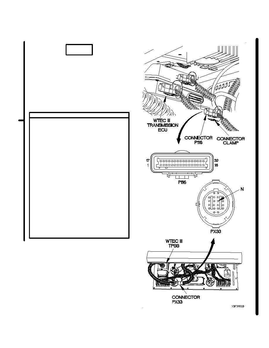
CONTINUITY TEST
(1) Disconnect connector clamp from
connector P116.
(2) Disconnect connector P116 from WTEC
III transmission ECU.
(3) Remove instrument panel assembly
for access (para 7-15).
(4) Disconnect connector PX33 from WTEC
III TPSS.
(5) Connect positive (+) probe of multimeter
to connector P116 socket 3.
(6) Connect negative (-) probe of multimeter to
connector PX33 socket N and note reading
on multimeter.
(7) Connect negative probe (-) of multimeter
to all other sockets in connector PX33,
one at a time, and note reading
on multimeter.
(8) Connect negative probe (-) of multimeter
to ground and note reading on multimeter.
(9) If continuity is not present in step 6, or
continuity is present in step 7 or step 8,
repair wire 124 (para 2-45) or replace
WTEC III dashboard cable assembly
(para 7-11).
Change 1
2-1822.7
|
|
Privacy Statement - Press Release - Copyright Information. - Contact Us |
