 |
|||
|
|
|||
|
|
|||
| ||||||||||
|
|
 TM 9-2320-366-20-2
WARNING
Wear appropriate eye protection when
working under vehicle due to the possibility
of falling debris. Failure to comply may
result in injury to personel.
CAUTION
Loose or dirty connectors may cause
intermittent loss of power to transmission
ECU and diagnostic codes to be logged.
Ensure that all connectors are clean and tight
before performing troubleshooting. Failure to
comply may result in incorrect test results.
Use care when testing electrical connectors.
Do not damage connector pins or sockets
with multimeter probes. Failure to comply
may result in damage to equipment.
NOTE
Inspect connector pins/sockets for damage,
corrosion, and serviceability. Check that
connector pins are not pushed back and
are capable of making good contact.
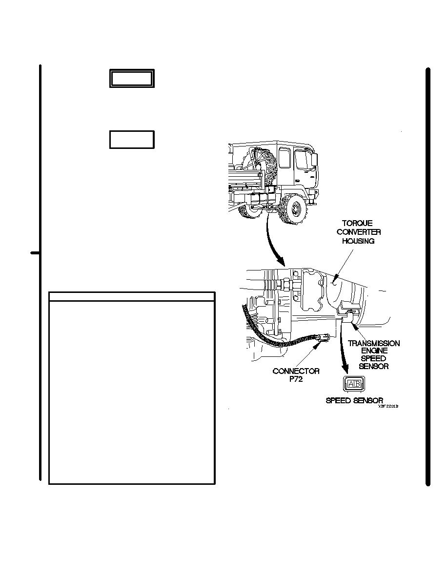
RESISTANCE TEST
(1) Disconnect connector P72 from transmission
engine speed sensor.
(2) Set multimeter to ohms.
(3) Connect positive (+) probe of multimeter to
pin A of transmission engine speed sensor.
NOTE
A good transmission engine speed sensor
will return a reading of 200-400 ohms
resistance as follows:
a. 200 ohms at - 40 F (- 40 C)
b. 300 ohms at 68 F (20 C)
c. 400 0ohms at 230 F (110 C)
(4) Connect negative (-) probe of multimeter to
pin B of transmission engine speed sensor
and note reading on multimeter.
(5) If good resistance is not noted, replace
transmission engine speed sensor
(para 7-52).
(6) Connect connector P72 to transmission
engine speed sensor.
Change 1
2-1713
|
|
Privacy Statement - Press Release - Copyright Information. - Contact Us |
