 |
|||
|
|
|||
|
|
|||
| ||||||||||
|
|
 TM 9-2320-366-20-2
CAUTION
Use care when testing electrical connectors.
Do not damage connector pins or sockets
with multimeter probes. Failure to comply
may result in damage to equipment.
NOTE
Inspect connector pins/sockets for damage,
corrosion, and serviceability. Check that
connector pins are not pushed back and
are capable of making good contact.
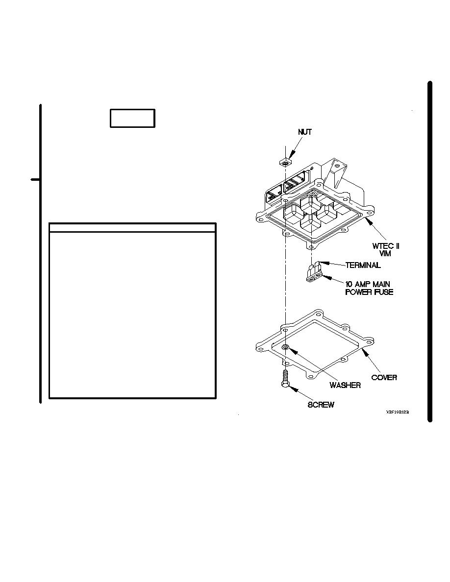
CONTINUITY TEST
(1) Remove seven screws and washers from
WTEC II VIM cover.
(2) Remove screw, washer, WTEC II VIM
cover, and nut from WTEC II VIM.
(3) Remove 10 AMP MAIN POWER fuse from
WTEC II VIM.
(4) Set multimeter to ohms.
(5) Connect positive (+) probe of multimeter
to one terminal on 10 AMP MAIN POWER
fuse.
(6) Connect negative (-) probe of multimeter
to other terminal on 10 AMP MAIN
POWER fuse and note reading on
multimeter.
(7) If continuity is not present, replace
10 AMP MAIN POWER fuse (para 8-6).
(8) Position WTEC II VIM cover on WTEC II
VIM with washer, screw, and nut.
(9) Install seven washers, and screws in
WTEC II VIM cover.
Change 1
2-1706.9
|
|
Privacy Statement - Press Release - Copyright Information. - Contact Us |
