 |
|||
|
|
|||
|
|
|||
| ||||||||||
|
|
 TM 9-2320-366-20-2
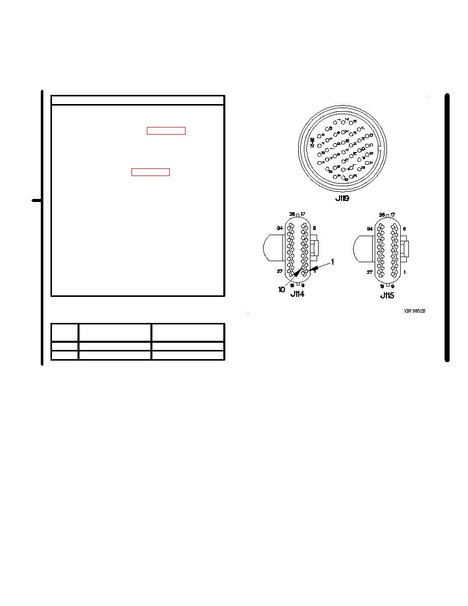
CONTINUITY TEST
(1) Set multimeter to ohms.
(2) Connect positive (+) probe of multimeter to
connector J119. Refer to Table 2-24. Main
Code 43 Sub Code 21 and 26 Low Side
Test Points.
(3) Connect negative (-) probe of multimeter to
connector J114 and note reading on
multimeter. Refer to Table 2-24. Main Code
43 Sub Code 21 and 26 Low Side Test
Points.
(4) Connect negative (-) probe of multimeter to
all other sockets in connector J114, one at a
time, and note reading on multimeter.
(5) Connect negative (-) probe of multimeter to
all sockets in connector J115, one at a time,
and note reading on multimeter.
(6) Connect negative (-) probe of multimeter to
ground and note reading on multimeter.
(7) If continuity is not present in step 3, or
continuity is present in step 4, 5, or 6,
replace WTEC II cab transmission harness
(para 7-137).
Low Side Test Points
Sub
Connector
Connector
Code
J114
J119
21
10
H
26
1
A
Change 1
|
|
Privacy Statement - Press Release - Copyright Information. - Contact Us |
