 |
|||
|
|
|||
|
|
|||
| ||||||||||
|
|
 TM 9-2320-366-20-2
CAUTION
Loose or dirty connectors may cause
intermittent loss of power to transmission
ECU and diagnostic codes to be logged.
Ensure that all connectors are clean and tight
before performing troubleshooting. Failure to
comply may result in incorrect test results.
Use care when testing electrical connectors.
Do not damage connector pins or sockets
with multimeter probes. Failure to comply
may result in damage to equipment.
NOTE
Inspect connector pins/sockets for damage,
corrosion, and serviceability. Check that
connector pins are not pushed back and
are capable of making good contact.
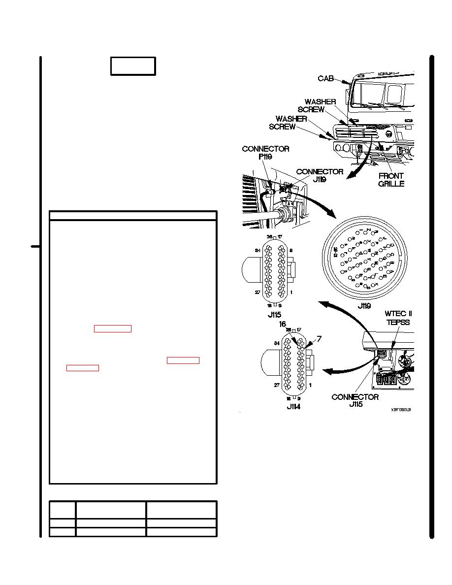
CONTINUITY TEST
(1) Remove two screws and washers from
front grille.
(2) Remove screw and washer from front grille.
(3) Remove front grille from cab.
(4) Disconnect connector P119 from connector
J119.
(5) Remove instrument panel assembly for
access (para 7-15).
(6) Disconnect connectors J114 and J115
from WTEC II TEPSS.
(7) Set multimeter to ohms.
(8) Connect positive (+) probe of multimeter
to High side socket of connector J119.
Refer to Table 2-23. Main Code 43 Sub
Code 21 and 26 High Side Test Points.
(9) Connect negative (-) probe of multimeter to
High side socket of connector J114 and
note reading on multimeter. Refer to Table
26 High Side Test Points.
(10) Connect negative (-) probe of multimeter to
all other sockets in connector J114, one at
a time, and note reading on multimeter.
(11) Connect negative (-) probe of multimeter to
all sockets in connector J115, one at a time,
and note reading on multimeter.
(12) Connect negative (-) probe of multimeter to
ground and note reading on multimeter.
(13) If continuity is not present in step 9, or
continuity is present in step 10, 11, or 12,
replace WTEC II cab transmission harness
(para 7-137).
High Side Test Points
Sub
Connector
Connector
Code
J114
J119
21
7
F
26
16
K
Change 1
|
|
Privacy Statement - Press Release - Copyright Information. - Contact Us |
