 |
|||
|
|
|||
|
|
|||
| ||||||||||
|
|
 TM 9-2320-366-20-2
CAUTION
Use care when testing electrical connectors.
Do not damage connector pins or sockets
with multimeter probes. Failure to comply
may result in damage to equipment.
NOTE
Inspect connector pins/sockets for damage,
corrosion, and serviceability. Check that
connector pins are not pushed back and
are capable of making good contact.
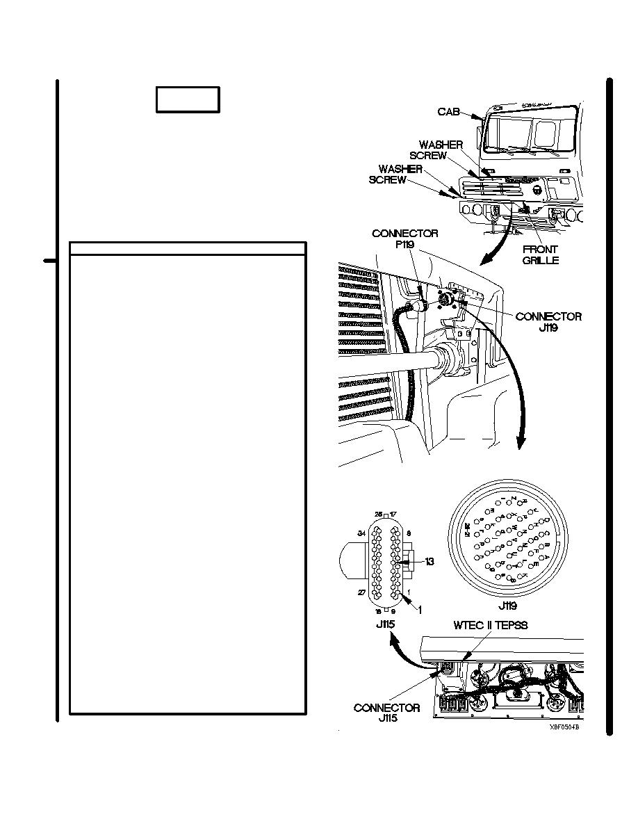
CONTINUITY TEST
(1) Remove two screws and washers from
front grille.
(2) Remove screw, washer and front grille
from cab.
(3) Disconnect connector P119 from
connector J119.
(4) Remove instrument panel assembly for
access (para 7-15).
(5) Disconnect connector J115 (top
connector) from WTEC II TEPSS.
(6) Install jumper wire from connector J119d
to J119a.
(7) Set multimeter to ohms.
(8) Connect positive (+) probe of multimeter
to connector J115-13.
(9) Connect negative (-) probe of multimeter on
J115-1 and note reading on multimeter.
(10) Connect negative (-) probe of multimeter to
all other sockets in connector J115, one at
a time, and note reading on multimeter.
(11) Connect negative (-) probe of multimeter to
ground and note reading on multimeter.
(12) Connect positive (+) probe of multimeter to
connector J115-1.
(13) Connect negative (-) probe of multimeter to all
other pins in connector J115 (except
J115-13), one at a time, and note reading on
multimeter.
(14) Connect negative (-) probe of multimeter
to ground and note reading on multimeter.
(15) If continuity is not present in step 9, or
continuity is present in step 10, 11, 13, or
14, replace WTEC II cab transmission
harness (para 7-137).
(16) Remove jumper wire from connector
J119d to connector J119a.
(17) Connect connector J115 to WTEC II
TEPSS.
(18) Install instrument panel assembly
(para 7-15).
Change 1
2-1617
|
|
Privacy Statement - Press Release - Copyright Information. - Contact Us |
