 |
|||
|
|
|||
|
|
|||
| ||||||||||
|
|
 TM 9-2320-366-20-2
TM 9-2320-365-20-2
CAUTION
Use care when testing electrical connectors.
Do not damage connector pins or sockets
with multimeter probes. Failure to comply
may result in damage to equipment.
NOTE
Inspect connector pins/sockets for damage,
corrosion, and serviceability. Check that
connector pins are not pushed back and
are capable of making good contact.
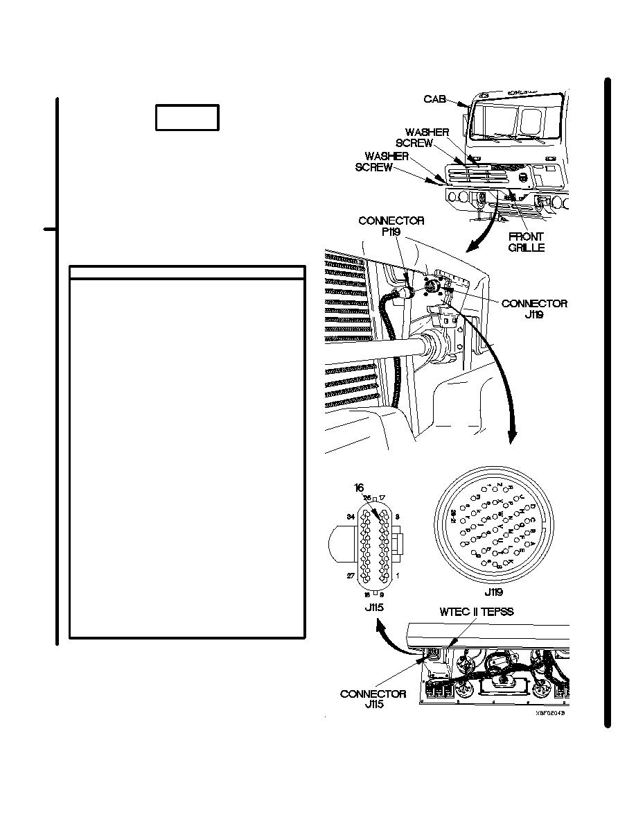
CONTINUITY TEST
(1) Set multimeter to ohms position.
(2) Connect positive (+) probe of multimeter
to connector socket J115-16.
(3) Connect negative (-) probe of multimeter to
connector socket J119s and note reading
on multimeter.
(4) Connect negative (-) probe of multimeter to
all other sockets in connector J119 and
note reading on multimeter.
(5) Connect negative (-) probe of multimeter to
ground and note reading on multimeter.
(6) If continuity is not present in step 3, or
continuity is present in step 4 or step 5,
replace WTEC II cab transmission harness
(para 7-137).
(7) If continuity is present in step 3 and no
shorts circuits are found, replace WTEC II
TEPSS (para 8-2).
(8) Connect connector J115 to WTEC II
TEPSS.
(9) Install instrument panel assembly (para
7-15).
(10) Connect connector P119 to connector
J119.
(11) Position front grille on cab with washer
and screw.
(12) Position two washers and screws in front
grille.
(13) Tighten screw to 48-60 lb-in. (5-7 Nm).
(14) Tighten two screws to 24 lb-in. (3 Nm).
(15) Clear diagnostic codes (para 8-4).
Change 1
2-1593
|
|
Privacy Statement - Press Release - Copyright Information. - Contact Us |
