 |
|||
|
|
|||
|
|
|||
| ||||||||||
|
|
 TM 9-2320-366-20-2
CAUTION
Use care when testing electrical connectors.
Do not damage connector pins or sockets
with multimeter probes. Failure to comply
may result in damage to equipment.
NOTE
Inspect connector pins/sockets for damage,
corrosion, and serviceability. Check that
connector pins are not pushed back and
are capable of making good contact.
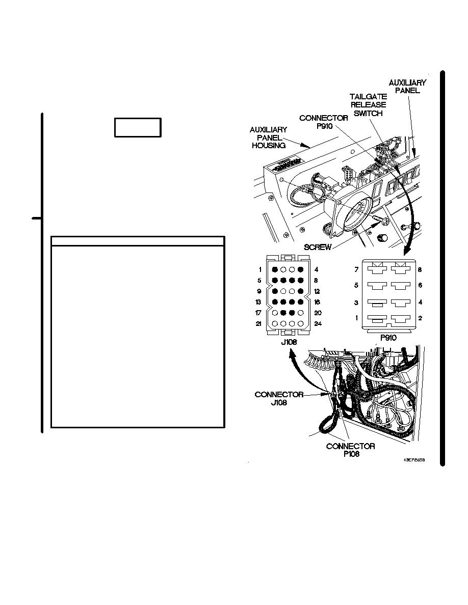
CONTINUITY TEST
(1)
Remove kick panel (para 16-3).
(2)
Disconnect connector P108 from connector
J108.
(3)
Set multimeter to ohms.
(4)
Connect positive (+) probe of multimeter
to connector P910 socket 1.
(5)
Connect negative (-) probe of multimeter
to connector J108 pin 8 and note reading
on multimeter.
(6)
If continuity is not present, repair wire
2045 from connector P910 socket 1 to
connector J108 pin 8 (para 2-45) or
replace auxiliary panel cable assembly
(para 7-58).
(7)
Connect connector P108 to connector
J108.
(8)
Install kick panel (para 16-3).
(9)
Connect connector P910 to tailgate
release switch.
(10)
Position auxiliary panel on auxiliary
panel housing with six screws.
(11)
Tighten six screws to 24 lb-in. (3N.m).
Change 1
2-1477
|
|
Privacy Statement - Press Release - Copyright Information. - Contact Us |
