 |
|||
|
|
|||
|
|
|||
| ||||||||||
|
|
 TM 9-2320-366-20-2
TM
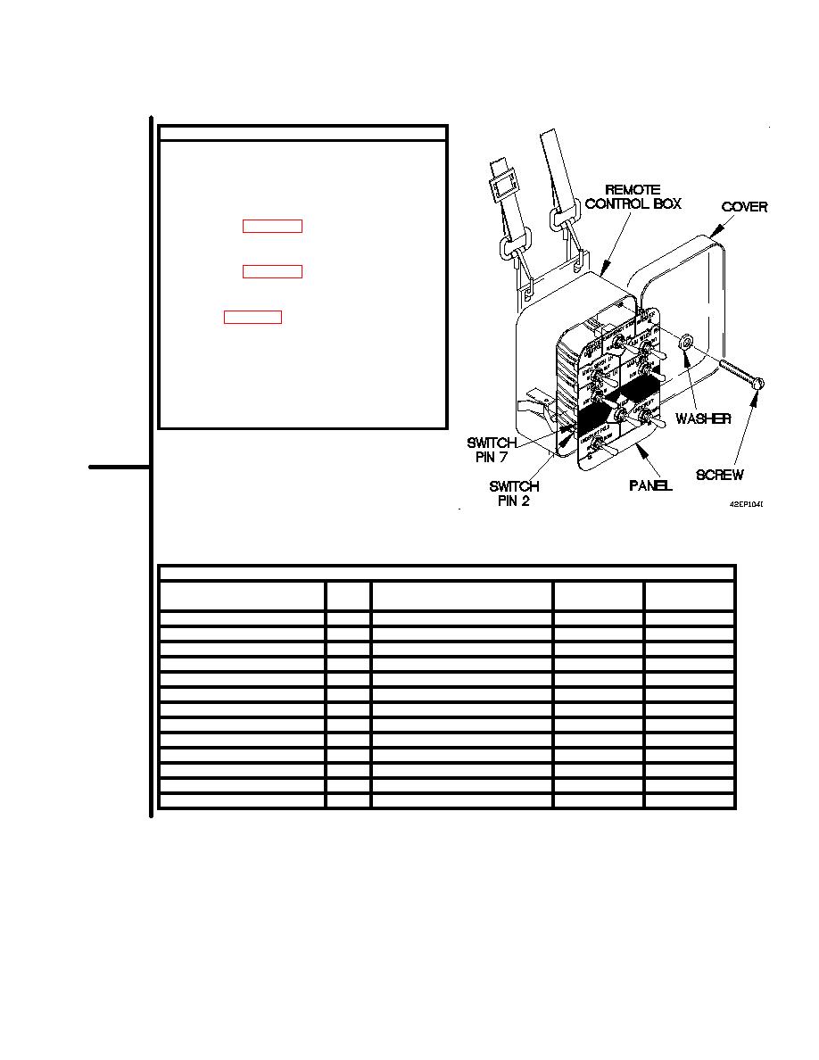
CONTINUITY TEST
(1)
Open cover on remote control box.
(2)
Remove four screws, washers, and panel from
remote control box.
(3)
Set multimeter to ohms.
(4)
Connect positive (+) probe of multimeter to
pin listed in Table 2-16. Remote Control Box
Switch Continuity Test.
(5)
Connect negative (-) probe of multimeter to
pin listed in Table 2-16. Remote Control Box
Switch Continuity Test.
(6)
Position remote control box switch to position
listed in Table 2-16. Remote Control Box
Switch Continuity Test and note reading on
multimeter.
(7)
If continuity is not present, repair wire
(para 2-45) or replace remote control box
switch (para 7-35).
(8)
Install panel on remote control box with
four washers and screws.
REF
Remote Control Box Position
Switch Pin
Switch Pin
Function
DES
and Switch Number
Positive (+)
Negative (-)
Underlift fold up
S15
UP
7
2
Stinger in
S14
IN
7
3
Underlift up
S13
UP
7
4
Main winch LH in
S10
IN
7
6
Main winch RH in
S8
IN
7
8
Main winch RH out
S8
OUT
7
11
Main winch speed RH high
S9
HIGH
7
12
Main winch LH out
S10
OUT
7
13
Main winch speed LH high
S11
HIGH
7
14
Underlift down
S13
DOWN
7
15
Stinger out
S14
OUT
7
16
Underlift fold down
S15
DOWN
7
17
Emergency stop
S7
KILL
9
10
2-1465
|
|
Privacy Statement - Press Release - Copyright Information. - Contact Us |
