 |
|||
|
|
|||
|
|
|||
| ||||||||||
|
|
 TM 9-2320-366-20-2
TM
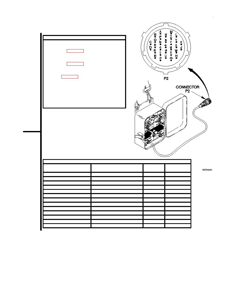
CONTINUITY TEST
(1)
Set multimeter to ohms.
(2)
Connect positive (+) probe of multimeter to
pin listed in Table 2-15. Remote Control Box
Continuity Test.
(3)
Connect negative (-) probe of multimeter to
pin listed in Table 2-15. Remote Control Box
Continuity Test.
(4)
Position remote control box switch to position
listed in Table 2-15. Remote Control Box
Continuity Test and note reading on
multimeter.
(5)
If continuity is not present, go to step 4 of this
fault.
(6)
If continuity is present, repair wire (para 2-45)
or replace M1089 remote control wiring
harness (para 7-117).
P2 Pin
P2 Pin
Function
Remote Control Box Position
Positive (+)
Negative (-)
Underlift fold up
UP
c
e
Stinger in
IN
c
f
Underlift up
UP
c
g
Main winch LH in
IN
c
d
Main winch RH in
IN
c
b
Main winch RH out
OUT
c
Y
Main winch speed RH high
HIGH
c
X
Main winch LH out
OUT
c
W
Main winch speed LH high
HIGH
c
V
Underlift down
DOWN
c
U
Stinger out
OUT
c
T
Underlift fold down
DOWN
c
S
Emergency stop
KILL
a
Z
2-1463
|
|
Privacy Statement - Press Release - Copyright Information. - Contact Us |
