 |
|||
|
|
|||
|
|
|||
| ||||||||||
|
|
 TM 9-2320-366-20-2
CAUTION
Use care when testing electrical connectors.
Do not damage connector pins or sockets
with multimeter probes. Failure to comply
may result in damage to equipment.
NOTE
Inspect connector pins/sockets for damage,
corrosion, and serviceability. Check that
connector pins are not pushed back and
are capable of making good contact.
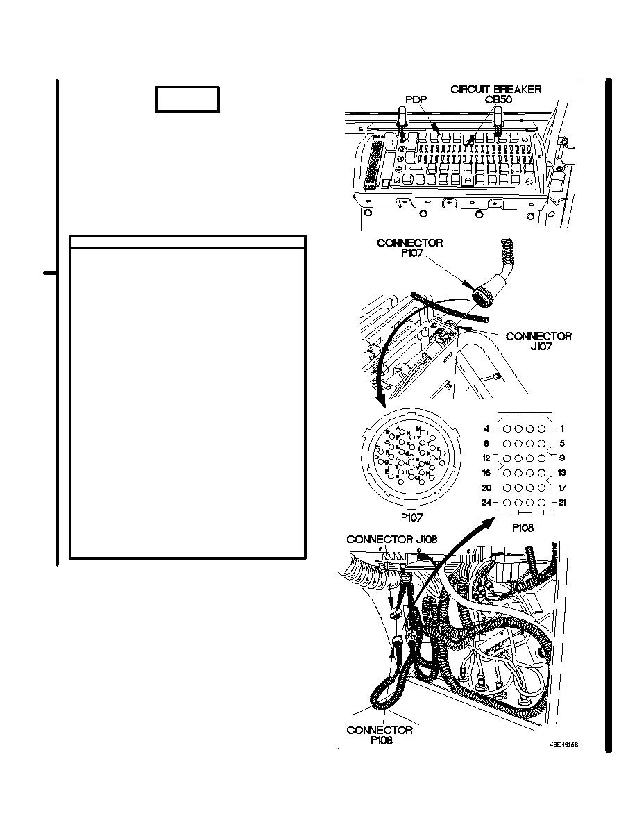
CONTINUITY TEST
(1) Install circuit breaker CB50 in PDP.
(2) Disconnect connector P107 from connector
J107.
(3) Set multimeter to ohms.
(4) Connect positive (+) probe of multimeter
to connector P108 socket 16.
(5) Connect negative (-) probe of multimeter to
connector P107 socket g and note reading
on multimeter.
(6) If continuity is not present, repair wire
2006 from connector P107 socket g to
connector P108 socket 16 (para 2-45) or
replace M1089 rear lights cable assembly
(para 7-104).
(7) If continuity is present, repair wire 9 from
connector J107 to terminal block TB9
(para 2-45) or replace M1089 control panel
power cable assembly (para 7-109).
(8) Connect connector P108 to connector
J108.
(9) Install kick panel (para 16-3).
(10) Connect connector P107 to connector
J107.
(11) Install wrecker control panel top cover
(para 14-4).
(12) Connect batteries (para 7-57).
Change 1
2-1450.27
|
|
Privacy Statement - Press Release - Copyright Information. - Contact Us |
